Add support for SM2135 as used in Action LSC SmartLed #6495
Comments
|
Great since there are many Shops in Europe :-) |

Experimental support for SM2135 (#6495)
|
VERY EXPERIMENTAL as I have many questions using the current documentation. I currently fail to flash these bulbs so I cannot test it yet. In order to use it you will need to add define USE_SM2135 to my_user_config.h or your override file. |
Add max current checks to SM2135 (#6495)
|
Great work arendst! I dumped the firmware of the E14 bulb so maybe there is a chance tuya-convert will be compatible soon. I'll test your experimental driver (probably sunday evening) and report my findings. Have to find a 15v psu first I guess, that's printed on the LED circuit board but I suppose 12v will due as well🤔 EDIT: Any specific information you want me to test? I noticed in the datasheet that RGB cannot be used simultaneously with W/YW? |
|
From what I read in the spes the address starts from 0xC0 1100 0000
|
|
@TimelessNL the 15V and Vin are different. |
|
mmh interesting... I can try to measure that, but I tried tuya-convert-new-api on my bulb (in parts) and guess what? It works just fine. So do we still need to know the voltage since any bulb can now be ota'ed? Also flashed my bulb with tasmota-dev and tried the experimental SM2135 support. Results:
When I set UPDATE: |

|
Regarding tuya-convert you just did you use python2 or python3? I think I have to sacrifice my bulb and try to open it up to find if it still uses the esp8266... |
|
@arendst can we flash ota over and over until we got the i2c driver part right? Is commandline i2c an option? else we need to listen the lsc talking to it. @TimelessNL my next trail and errors will be after this weekend (drukke agenda) |
|
The fact the chip respons to commands means the I2C address is just fine. All that needs to be done is figuring out the color positions in the string and chip timing. Ota can be done many times but it makes more sense that I try to get it working as that will solve the issue much quicker. |
|
@arendst not sure if you noticed but I did figure out why 3 different brands of my bulbs didn't work with the new branch of tuya convert. Simply changing the build on my Raspberry Pi from Stretch to Buster fixed it. (Timing issues maybe?) I posted about it in the long thread discussing flashing the bulbs. You might have some luck with yours and not destroy it. EDIT: Add link - ct-Open-Source/tuya-convert#273 (comment) |
|
Thx. I did use Buster on a latest Raspberry Pi but failed. I'll do it over again tomorrow and report. |
I just installed ubuntu 18.04 on a spare laptop and removed Please take note that I use the new-api branch. Only that one works with the GU10 and E14 bulbs.
You bought the LSC E14 or GU10 bulb right? It would be strange that they manufactured a RTL and ESP version 🤔 because I bought some today and they did contain the ESP like my first sacrificed bulb did. |
|
@TimelessNL do you got an E27 also? Could you triple check that it won't flash, now you got it up and running? |
|
@ggaljoen you disassembled the E27 bulb right? I saw the picture and it shows a Tuya WR3L which according to the datasheet is a RTL8710: User-Manual-4311156.pdf I could have tested it only if they where in stock, all E27 bulbs in my local area are pretty wanted 😆. The WL3L can however be replaced with a ESP (pin compatible) because that's what I did with the siren. But I doubt that is worth it since there are better E27s on the market that are better equipped than 6 5050 style RGB LEDs. |
|
Just got two E14 bulbs and will try to update one and continue work on the driver. |
|
Great. Good luck! |
|
Well flashing went easy using kueblc's new-api version. Now on to the next phase... |
|
How is the next phase going arendst? Did you find anything interesting? |
|
No luck yet. Had no time today as the shutter needed to get merge. What I found out so far is that the chip responds with all i2c addresses when scanned - not good. Unable to send anything to the chip. Only tested on pre-2.6.0 Next actions will be
|
|
Ah that's unfortunate. I was using 2.5.2 last time but did not actually scan for adresses. But were you able to get any light out of it? Because my bulb actually produced colors in different brightness levels so your sketch seemed to be able to talk to the chip in some manner. I will try tomorrow evening to see if I can work out some buspirate magic (been a long time though so I may be a bit rusty). Also something that came to mind, I was looking at the ESP sdk repo from tuya which did not contain that much code. But since the E27 RGB contains the RLT chip and the RTL repo contains many more examples we might find something interesting there, but that's just a guess. |
|
Be carefull with connecting something to the bulb; the gnd is on some level connected to your L or N 230V. As Arendst stated, use opto's to uncouple from the mains wires/voltages! Got the Magic black smoke escaped that way... |
|
Thanks for the warning, I've seen your post earlier. That's why I was planning to power the chip from my bench power supply. That makes it even saver for myself to probe this thing. |
|
Progress!! After a day of rest and re-applying power to the bulb it now responds to color commands. Still no correct relation but at least I have some kind of communication going. |
|
I was trying some experimental writes to this chip and it seems to me that RGB cannot be used with CW. Also on the last page of the datasheet it somewhat states (in chinglish)
So I suppose this is different than how Tasmota normally handles RGBCW right? |
|
You're right, Byte 2 selects RGB of WY mode... |
|
If Tasmota is flashed and there is no visible AP -> |
|
As mentioned in the update, was able to access the vtrust-recover, so some flash was not OK before. Luckily tuya-convert has some kind of recovery mode. Anyhow, Is my idea on creating the firmware correct? "Now created a custom bin file with tasmocompiler. I should just need to put in the "#define USE_SM2135" in custom parameters and select development/2.6.x/English/Sonoffs?" |
|
No, because the firmware has to be <500k for initial flash with Tuya Convert. |
|
Thanks @Jason2866, I kinda missed the <500k part. Anyhow, I was able to flash eventually. For reference of others:
Now you can control the white in web UI, color needs to be done via console. Connect as any other MQTT device to your setup. @TimelessNL , would you have happened to make some progress with the brightness on the RGB part? It seems to be less bright compared to stock fw. Is this configurable as a custom parameter as well in tasmocompiler? |
|
Please don't take my comment in any negative way, but please keep the discussion about work done on the SM2135 and not about 'tuya-convert' or ' general how to compile tasmota' stuff. The wiki should be sufficient for those questions. Unfortunately I don't have direct access to a thermal camera from work this week. Probably next week because then my personal unit arrives. So it will take a little longer to get exact measurements of the LEDs and SM2135. I'm currently testing it with a laser temperature gun but this measurement is quite imprecise. |
|
I'v compared the intensity visually between a tuys standard bulb and the Tasmotized one. I see no real difference but the tasmotized one may seem a bit more faint. The Warm and Cold whites look the same to me. If you want to experiment with the intensities just change line 54 in file xlgt_04_sm2135.ino while keeping an eye (and a hand) on the temperature. |
|
I did notice that the white and yellow intensities are not identical. 50% yellow does produce allot more light than 50% white. It's also funny to see when they are both on at the same time they produce less light than when only one of them is on. Don't know it this is also with the original tuya firmware though. |
|
The total value of yellow and white is 255. So if yellow is 255, white should/must be 0 and the other way round. The code makes sure that any mixture of yellow/white will always be at most 255. This is normal practice for mixing colors as you do not want the total lumen/lux to change. It also makes sure the chip does not get overheated as documented in the datasheet. I think instead of measuring temperature it makes more sense to measure lumen/lux. Once it looks fine to the eye it won't make sense to compare with tuya as it probably ends up in a lot of additional code just to mimic the tuya colors, which by the way are not that correct either. |
|
First off - THANK YOU ALL SO MUCH! I've been beating my head against a wall for months on these: https://www.amazon.com/gp/product/B07HG199VX/ref=ppx_yo_dt_b_search_asin_title?ie=UTF8&psc=1 Got one working today. I had 8, and destroyed 2 trying to figure them out. Can't tell you how many hours I spent on this. It appears to be a four channel RGB + WW light. Right now, the color channels are mixed up, but I couldn't care less because it's actually working. I'm sure there's a way to remap the colors. If there is any info at all you need, let me know. I have the original Tuya firmware. |
|
Thanks for adding support of these leds. I've flashed a few now for fun,. 2 of 5 have some weird issue (all same firmware and settings except the (host)name.) It seems like these "faulty" ones have some random default data in the driver after a power-cut (switch). Like they don't retain the power - and color settings. You'd have to cycle all color/light settings to calibrate the light. |
|
The LSC GU10 bulbs seem to be quite nice with their lighting options. However, as mentioned, the RGB is very dim. To be honest it's also quite dim with the original LSC firmware. I've taken measurements with my FLIR camera and the bulb isn't getting hot at all switching to full Red, Green, or Blue compared to having full brightness with the CW or WW LEDs. So I think there's room for improvement with regards to the RGB currents. I know we're not supposed to ask general compilation stuff but here I go anyway: I've followed the guide at https://github.com/arendst/Sonoff-Tasmota/wiki/Beginner-Guide---Create-your-own-Firmware-Build and am just wondering what exactly I need to change (besides the xlgt_04_sm2135.ino) to build a 'generic' firmware. I mean, the user_config thing has a bunch of settings for WiFi and MQTT and such, is this really necessary to fill in if I already have tasmota running on the bulbs? Basically I just want to play with the SM2135_**MA values, flash, and put my FLIR and LX meter on it to see if we can make this bulb behave better than it did from the factory. I'd love to have PM'd someone about a simple question like this but alas GH doesn't have that option. |
For support you have the Tasmota Support Chat |
|
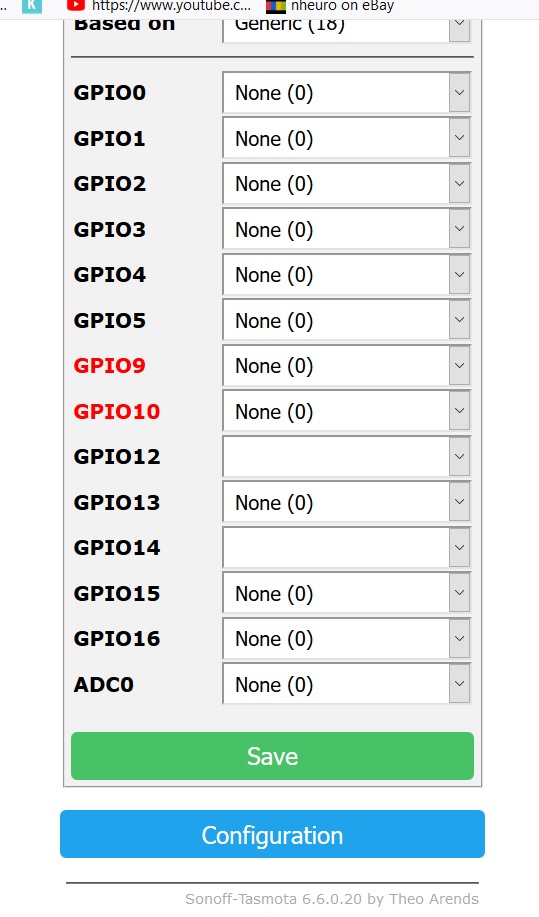
I updated to 6.6.0.20 and did {"NAME":"LSC RGBCW LED","GPIO":[0,0,0,0,0,0,0,0,181,0,180,0,0],"FLAG":0,"BASE":18} |
|
Usually, if the pin names do not appear in the dropdown then the binary does not include support for it. |
|
See releasenotes which binary supports your sm2135. |
|
Solved at Discord. He used Sonoff-Basic. After upgrading to sonoff.bin it works as expected.... |
|
So I've done some measurements and comparisons with the original LSC firmware and the Tasmota build. I've measured temperature and light output for each channel in the same condition for each bulb. Output (in lux): Temp (in Celcius) after 10 minutes: Temp (in Celcius) after 20 minutes: Temp (in Celcius) after 30 minutes: The Warm White and Cold White have less heat but also less light output so I'm guessing the mA can be upped a bit. Regarding the RGB values they are the same on both firmwares, however looking at the temperature I guess the mA can be upped as well, making the bulb perform 'better' with Tasmota compared to the original firmware. |
|
@redahb thx. To increase current you might want to change line 54 in file xlgt_04_sm2135.ino from in and redo your measurements. Pls report back if the results compare better. |
|
New results: I upped the CW/WW tot 15mA and this brought the WW to 4300lx and CW to 5000lx, which is pretty much spot on with the original firmware. So my guess is 15mA would be the optimal 'same-as-factory' setting. Personally I like the lesser temperature with 10mA (10 degrees is quite a lot) because in my house GU10 bulbs are rarely lighting a room by themselves (it's always a cluster of 2 or more) so I don't need the full brightness. I'll leave the decision up to you ;) RGB is a different story. As stated before, the RGB values from Tasmota vs LSC firmware are a tad bit dimmer but not by much. If you didn't have a lux meter you wouldn't notice. Having said that, I've bumped up the mA in increments up to 40 mA but didn't know if I should push further. What I'm noticing is:
Conclusion: Basically with 40mA Red overshoots, Green isn't performing like the original firmware yet, and Blue is sort of on par. I would have expected a much bigger difference in brightness but to the naked eye I can barely see difference between 20mA and 40mA. With CW/WW, I can see a difference by only a 5mA increase. As it stands, both with LSC firmware and Tasmota firmware the RGB colors are pretty weak compared to other bulbs. That's disappointing, but as I'm not knowledgeable about the SM2135 chip at all, I have no idea if we should and can push the RGB channels further. Temperature probably isn't the only limit I guess? And do we want this bulb to behave 'better' on Tasmota or do we want to copy the factory specifications? Again, decision up to you ;) |
|
Thx again! I'll up the CW/WW to 15mA and leave the RGB as they are saving power while no real difference in lux. |
Increase SM2135 CW/WW intensitity (#6495)
|
Hello, |
|
I have 2 LSC GU10 spots and flashed them with Tasmota. I have a connection, can upgrade the firmware but can't turn turn the lights on or off. This is my setting. One light worked but stopped working after a power cycle. I can still reach them with wifi (Tasmota) |
|
Same here only the e14 rgb bulb |
|
Did you include support for the sm2135? I may not be compiled in and therefore wont work. |
|
Thanks , i saw the sm2135 but have not figured out how to flash it to the bulb or where to put it |
|
What you mean? The .bin has support for the sm2135 chip or it doesn't. There is no separate file you have to flash. |
|
Please, address this to the Tasmota Support Chat. The chat is a better and more dynamic channel for helping you. Github issues are meant for Tasmota Software Bug Reporting. Please check the Contributing Guideline and Policy and the Support Guide. Thanks. Support InformationSee Wiki for more information. |
Extend Tasmota with support for SM2135 five channel intelligent dimmer led with constant current driver interfaced using I2C as used in Action LSC Smart Leds (https://www.action.com/nl-nl/p/lsc-smart-connect-slimme-multicolor-ledlamp-2/)
SM2135E_zh-CN_en-US_translated.pdf
See https://www.mikrocontroller.net/topic/479796#5950544 for background info.
The text was updated successfully, but these errors were encountered: