-
Notifications
You must be signed in to change notification settings - Fork 6
Build Guide (Wired)
The wired build makes use of an Pro Micro microcontroller board and the QMK Firmware
| Part Name | Amount | Notes / Link |
|---|---|---|
| PCB | 2 | See the release page for the latest Gerber files or use KiCad to generate them |
| Top Plate | 2 | For a sandwich-case build. See the release page for the latest Gerber files or use KiCad to generate them. Note that the top and bottom plate are designed to be little bit larger than the PCB of the keyboard itself. |
| Bottom Plate | 2 | For a sandwich-case build. See the release page for the latest Gerber files or use KiCad to generate them. Note that the top and bottom plate are designed to be little bit larger than the PCB of the keyboard itself. |
| Pro Micro | 2 | or a compatible microcontroller board |
| Microcontroller Sockets | 4 | (Optional) |
| Diodes (e.g. 1N4148) | 40 | You can either use through hole or surface mount diodes e.g. https://www.aliexpress.com/item/32334222067.html |
| Switches | 40 | Only Kailh Choc switches are supported (PG1350) |
| Hot Swap Sockets | 30 |
(Optional) e.g. https://aliexpress.com/item/33023283633.html |
| TRRS connectors | 2 | The same type which is used in other split keyboards like the Corne or Kyria. Technically even TRS should work as only serial communication is supported between the halves e.g https://aliexpress.com/item/32869968774.html |
| Tactile push button | 2 |
Technically optional: you can use metal tweezers whenever you need to reset the microcontroller. https://aliexpress.com/item/10000184124465.html |
| TRRS Cable | 1 | A TRS cable does also work e.g. https://aliexpress.com/item/4000291134188.html or if you preferer it a longer one. |
| M2 Case Spacers | 14 | The height depends on whether you are going to use hot swap sockets and/or a TrackPoint module. I am using 6mm spacers together with hot swap sockets and a TrackPoint |
| M2 Guard Spacers | 4 |
Optional: Spacers for an acrylic glass shield. The length depends on the socketing of the microcontroller / display. I am using 8mm long spacers |
| M2 Screws | 36 | For the M2 spacers (plate & guard) |
| 4.7kΩ Resistor (I2C) | 2 | Only required if you a want to use an OLED display and/or linear actuator. |
| OLED Display | 2 |
(Optional) Use a 0.91 inch display e.g. https://aliexpress.com/item/32712441521.html |
| Linear Actuator | 1 |
(Optional) Only supported on the master side (by default right halve). DRV2605L Linear Actuator Haptic Breakout – Pimoroni |
| 4.7kΩ Resistor (TrackPoint) | 2 | Only required if you are going to use a TrackPoint |
| 100kΩ Resistor (TrackPoint) | 1 | Only required if you are going to use a TrackPoint |
| 2.2uF Capacitor (TrackPoint) | 1 | Only required if you are going to use a TrackPoint |
| TrackPoint | 1 |
(Optional) Only supported on the master side (by default right halve) The PCB is designed for a TrackPoint of a Thinkpad X230S, X240, X240S, X250, X250S, X260 or X270 Not personally tested: https://aliexpress.com/item/1005003581279881.html |
| TrackPoint Stem Extension | 1 | A stem extension for the TrackPoint is required. The hole in the top plate between the two inner columns is only 2.6mm in diameter and the hole between index and middle finger column has a diameter of 6mm. I am using a labret piercing as stem extension between the two inner columns. It is glued onto the TrackPoint module and is 6mm long and has a diameter of only 0.8mm
|
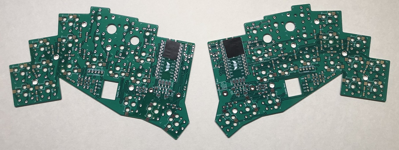
The PCB is reversible and it is easy to solder a component on the wrong side if you pay not attention to it. Tipp: mark the front/top side by a piece of tape in order to remember which side is which.
The diodes have to be soldered on the back/bottom of the PCB. Make sure you have the orientation right. The end with the line is cathode (-) and it should go in the direction of the "arrow" symbol on the PCB
| Surface mount diode | Through hole diode |
|---|---|
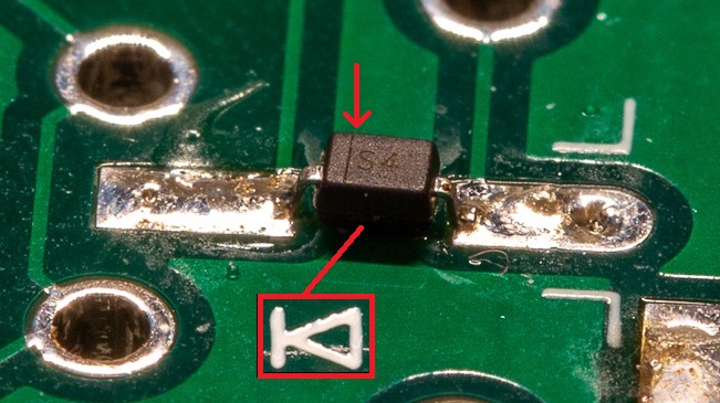 |
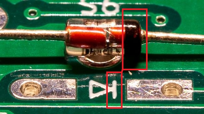 |
The use of hot swap sockets is optional. They must also be soldered on the back of the PCB like the diodes
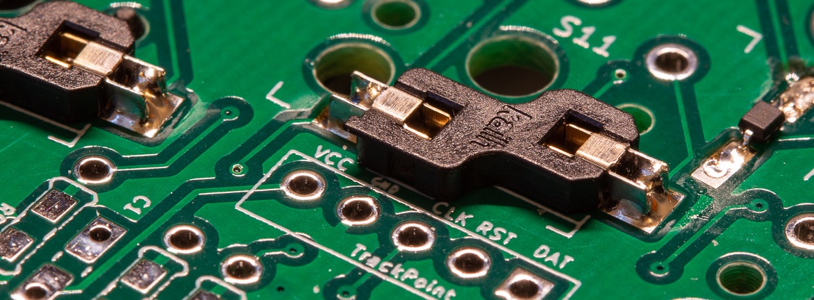
The resistors R1 and R2 (between thumb key and inner index column) are only required if you are going to use a display and / or a linear actuator. The have also to be soldered on the back of the PCB like the diodes and hot swap sockets.
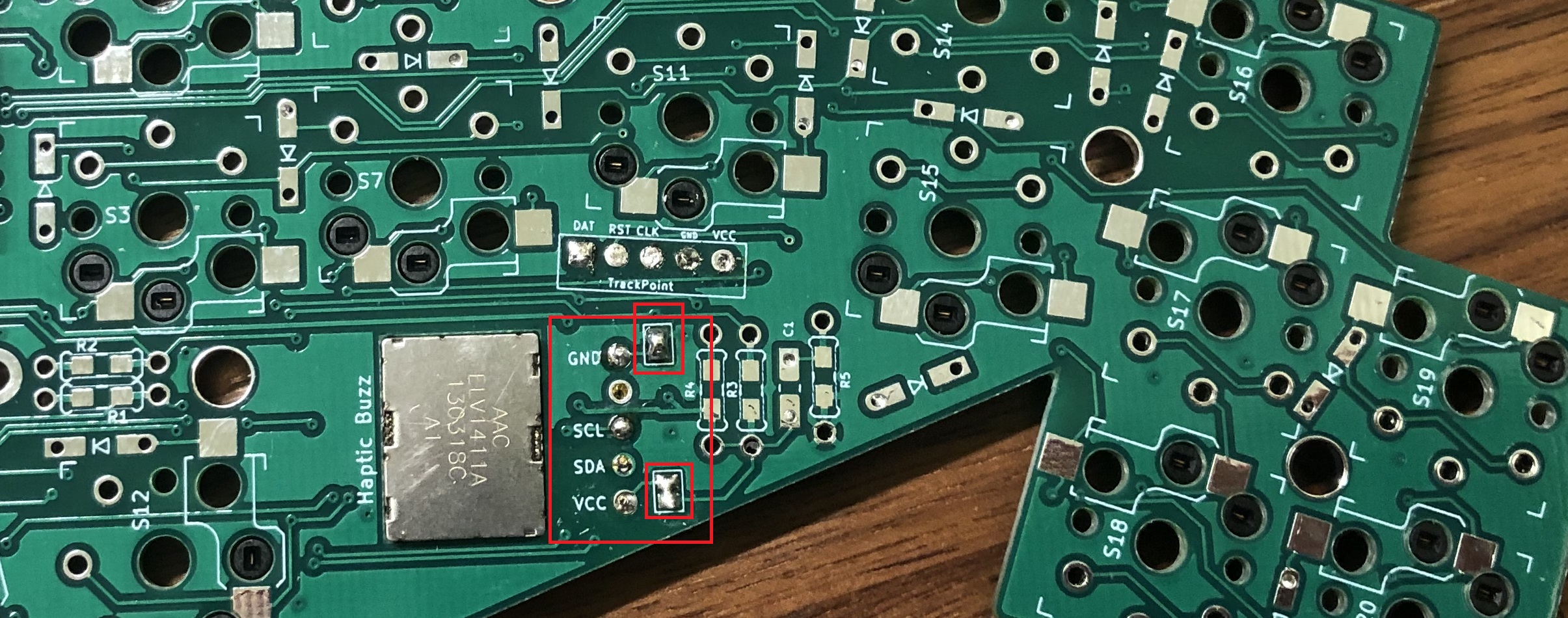
The linear actuator haptic breakout can only on the master halve be used. It should be inserted from the bottom. I also put some insulation tape between it and the PCB. Only the pins which are labeled on the front of the PCB must be soldered. Note also the two jumper pads. Those have to be bridged on the front of the PCB.
You have to bridge the OLED jumpers if you want to use an OLED display. They are right below the microcontroller footprint and have to be bridged on the front side of the PCB
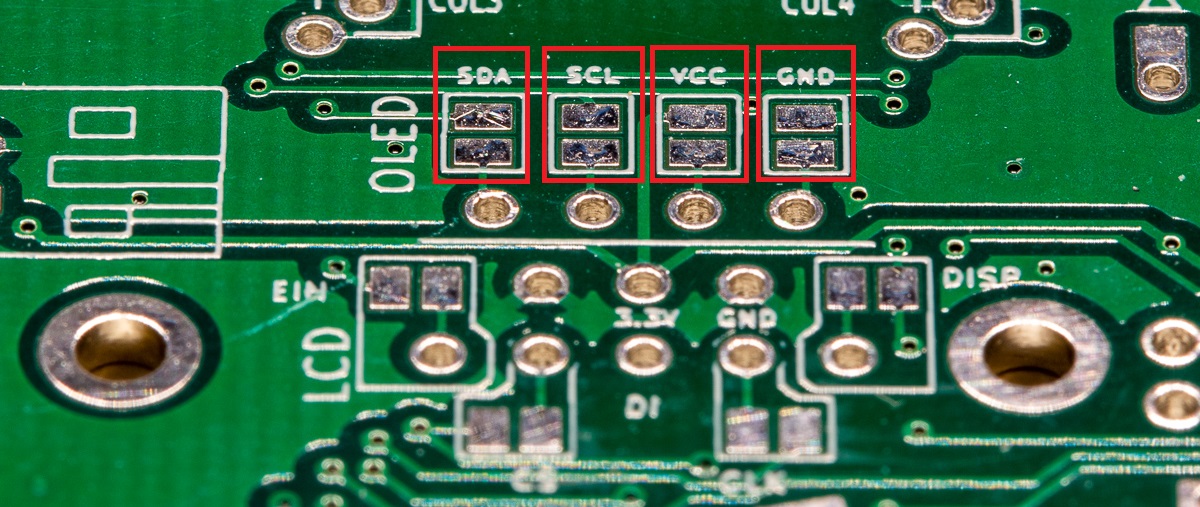
Note: in the image above are the jumpers not bridged because I already had assembled the keyboard when I took the pictures for the guide and was not able to take a good picture of the bridged jumpers and used therefore an image of a spare PCB
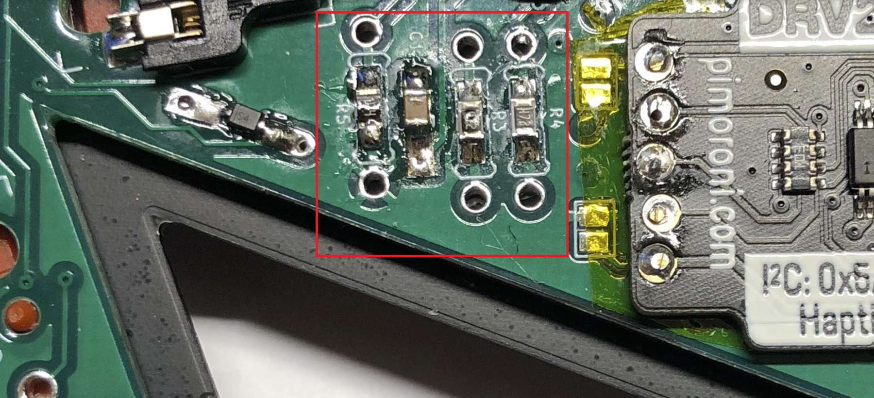
The TrackPoint reset circuit is required if you are planning to use a TrackPoint. Note that the TrackPoint is only on the master halve supported. Solder the resistors R3 (4.7kΩ), R4 (4.7kΩ) and R5 (100kΩ) and the capacitor C1 (2.2uF) also on the back Side of the PCB
Now it is time to solder on the TRRS socket and optionally the reset button. Use a piece of tape to fix them on the front side of the PCB and solder from the bottom side.
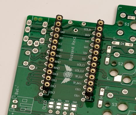
Socketing a microcontroller is quite useful. It makes it easier to remove the microcontroller later in case you would want to reuse it if it should break (the USB port on a Pro Micro is easily damaged).
Align the microcontroller/sockets with the outline columns of the pads. Which pair of rows you need to solder the controller to will be different depending on which half you solder it to. The microcontroller always faces with its backside up.
| Sockets | Microcontroller |
|---|---|
 |
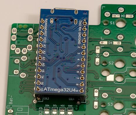 |
Important: If you are going to use a TrackPoint or are planning to maybe use one in the future than make sure to already insert the the screws for the TrackPoint from the front of the PCB (marked blue in the image below). After installing the top plate, it is no longer possible to insert the screws for the TrackPoint. It is only possible to tighten the screws with a small screwdriver because a screw head is to big to go through the hole of the top plate.
Install the switches through the plate and make sure they sit fully seated and solder them in case you are not using the hot swap sockets. It is easier when you start with a switch near each corner and working your way to the center.
I trimmed the four switches around TrackPoint to module to mount it later as flush as possible to the PCB (marked red in the image below). The stem are short enough and only the housing had to be cut off a little together with the supportive pins on either side.
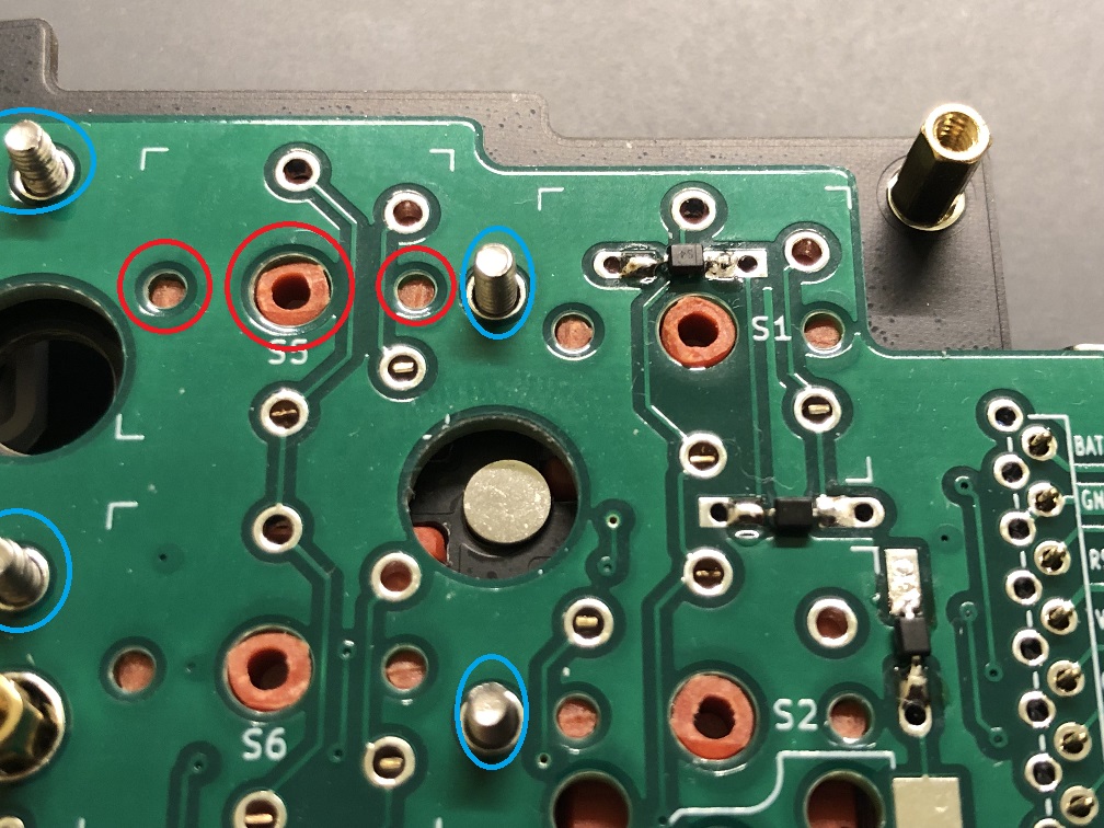
I am using a labret piercing as stem extension (6mm long and with a diameter of 0.8mm). It can be attached to the TrackPoint with a drop of super glue. Additionally you can roughen the surface of the labret piercing with a file. The ribbon cable is to short and has to be removed. Do not apply to much pressure when removing it as you can tear of the pads. Use a solder iron to remove one lane of the cable at a time.
| TrackPoint with extension | Back of TrackPoint |
|---|---|
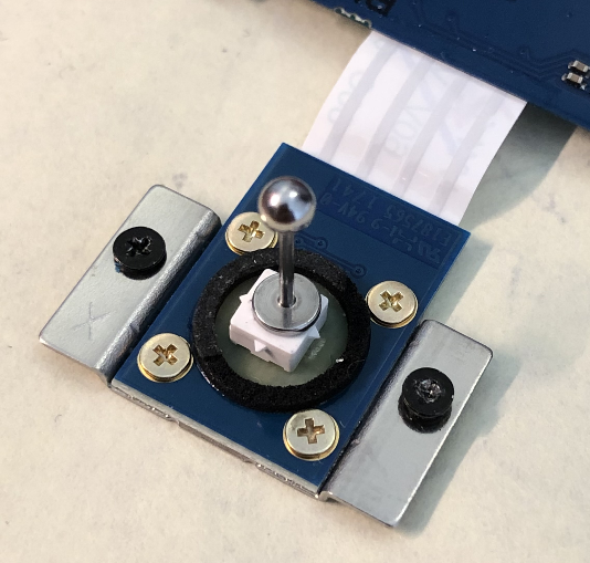 |
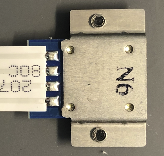 |
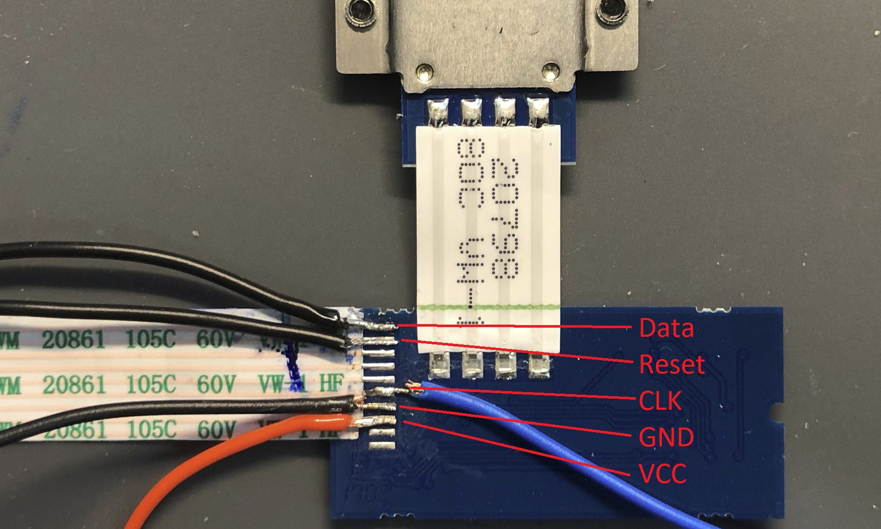
I used a TrackPoint module of an defective ThinkPad X240. In the picture below you can see the pinout of the module. Take care when soldering the wires to it. The pads are quite small and after solder I used clear nail polish to avoid unwanted shorts and secured the wires with some hot glue and a shrinking tube.
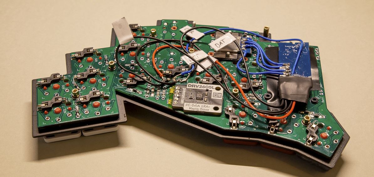
Screw off the ball of the piercing before mounting the TrackPoint to the PCB. It is recommended to use some tape between the PCB and the TrackPoint module to avoid any shorts.
The TrackPoint circuit board can be placed below the microcontroller board. I added here also some tape to avoid any shorts. The wires can than be solder the keyboard PCB at the designated TrackPoint pins.
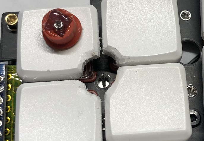
I cut off the edges of the switches to make space for the TrackPoint rubber can. The used hot glue to secure the ball of the labret piercing to the rubber cap. It can then be screwed on/off.
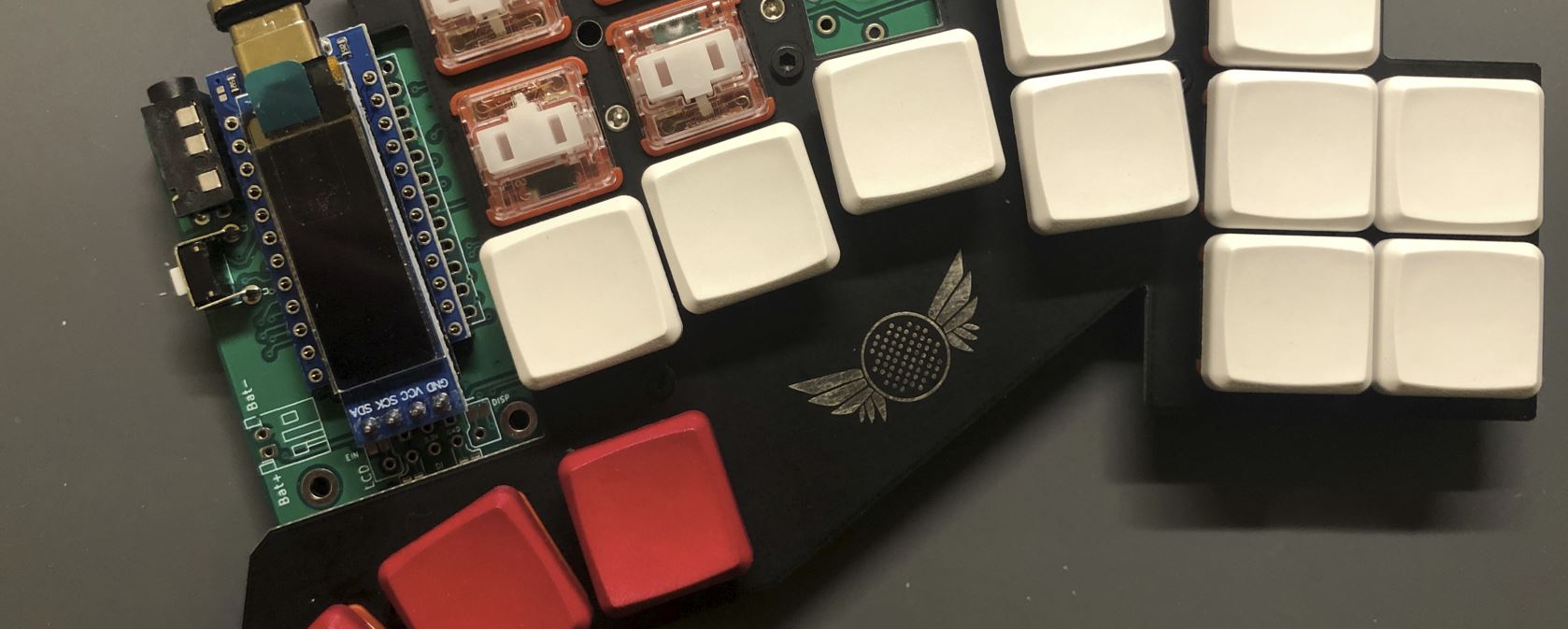
As with the microcontroller it can also be useful to socket the OLED display. Place it on top of the microcontroller and solder it from the bottom. Optionally you can also add an OLED guard. I am using dark acrylic glass and 6mm spacers. I also added some black tape on the back of the guard to let only the OLED shine through.
Finally the bottom plate can be screwed on and you are finished with your build (after adding your keycaps)!
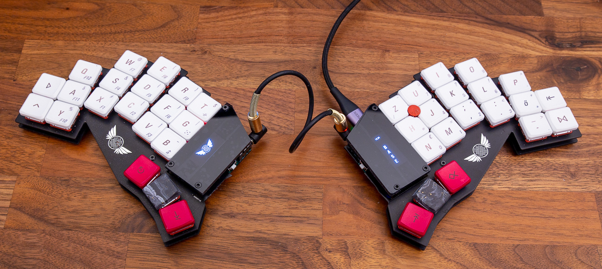
See https://github.com/qmk/qmk_firmware/tree/master/keyboards/buzzard for the firmware.