This project reverse engineers radio frequencies (RF) from a ceiling fan remote control using RTL-SDR (software defined radio), SDR#, an audio editor (audacity) and replays the signals using an Arduino micro controller with an RF transmitter.
We will be using a cheap digital TV/Radio USB receiver dongle to receive signals sent by the remote control which will then be demodulated and recorded with SDR#, a software defined radio program. We will analyse these audio clips in Audacity, an open-source audio editor to understand the information being transmitted before reconstructing the signal in software and replaying it via an Arduino microcontroller with an RF transmitter. Finally, we will have the Arduino serve as a basic HTTP server (using an Ethernet shield) which will allow us to send commands to the target device via a web page.
- An RF controlled device as the target device. Any remote device using ASK to transmit data will do.
- A RTL-SDR TV dongle to detect the RF signal(s) (c£4).
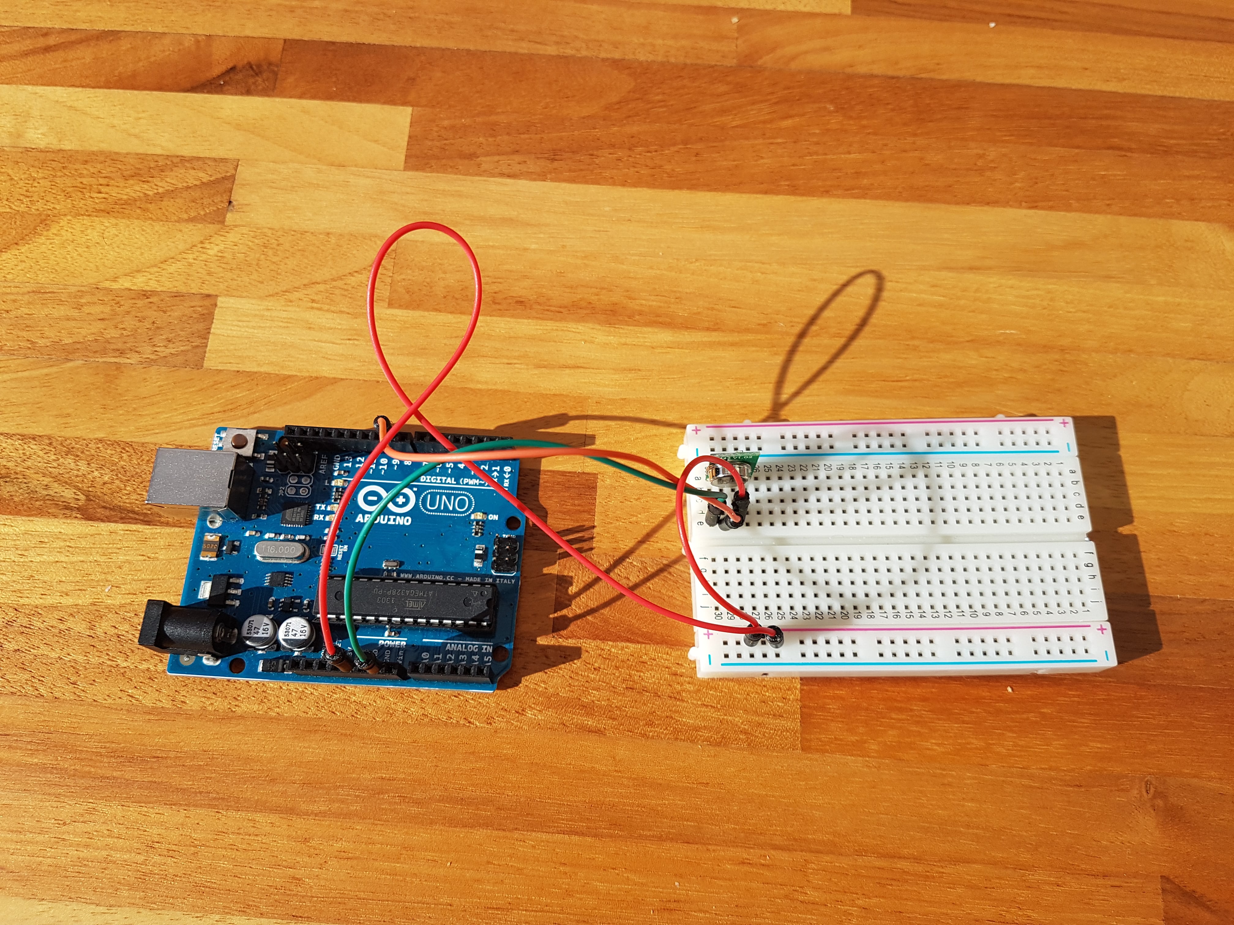
- An Arduino Uno to replay/transmit the RF signal (c£20).
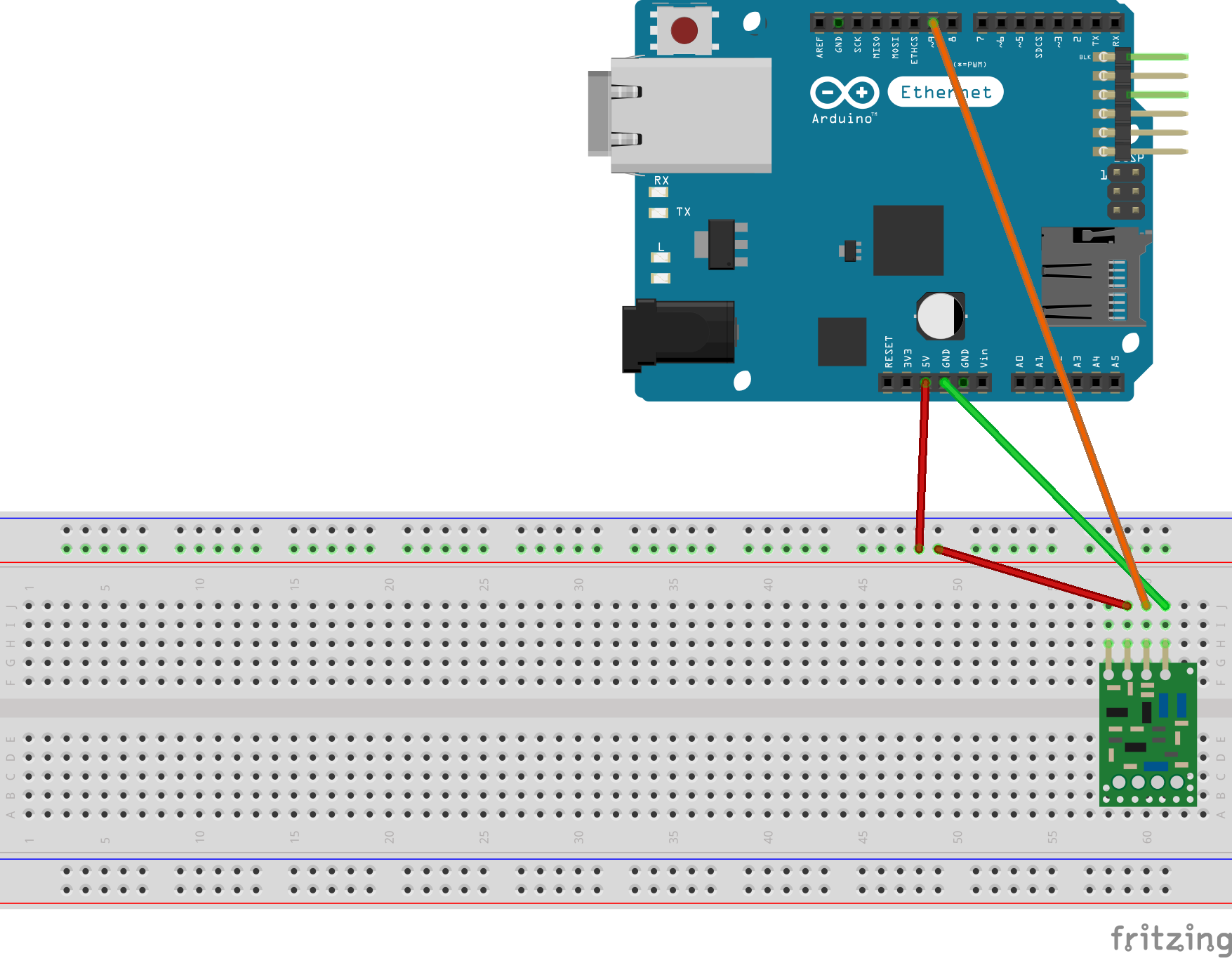
- An RF transmitter module (c£3).
- SDR# to listen for and record the RF signal (free).
- Audacity to analyse the RF packets (free). We are essentially using this as a basic logic analyser to inspect the waveforms sent by the remote.
- Arduino IDE to program the microcontroller to replay RF signals (free).
- An internet browser such as Google Chrome (free).
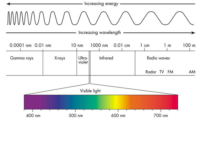
RFs are electromagnetic waves that lie in the range from 3 kHz to 300 GHz, comfortably at the right of figure 1 (low energy wavelengths).
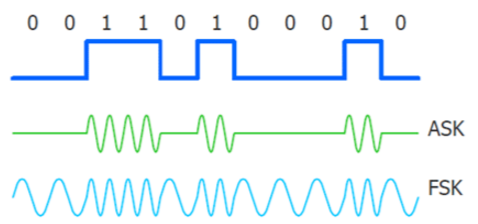
Modulation refers to the method used to encode digital data in a radio signal. The dark blue line in figure 2 shows a square wave representation of some digital information (1s and 0s) that we want to send or receive. To encode this information, a number of methods can be used, the most popular of which are Amplitude Shift Keying (ASK) and Frequency Shirt Keying (FSK) shown in light blue and green. These terms should be more familiar than they first appear; AM and FM radio use these encoding methods respectively; Amplitude Modulated and Frequency Modulated radio respectively.
a. Amplitude Shift Keying (ASK). The signal changes amplitude (signal strength or wave height) while the frequency remains constant.
b. Frequency Shift Keying (FSK). The signal changes frequency (wavelength) while the amplitude remains constant.
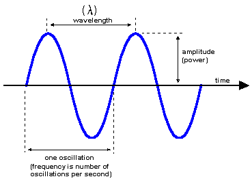
The biggest difference to note is that the ASK signal doesn't change frequency, rather it changes amplitude; in figure 2 ASK's signal goes quiet (off) to send a zero and 'loud' (on) for a one. Our RF remote (and many other basic devices) uses a variation of ASK called On-Off Keying (OOK) that has no carrier signal for logic zero (more below). In contrast, FSK alters its frequency oscillating around its base frequency to transmit data but does so at a constant amplitude. FSK is actually switching frequencies slightly (within a few hundred kHz) to convey information. Consider tuning to your favourite FM radio station which operated at 98.5 FM; your radio is actually listening for signals in a range around 98.5Mhz. Because of the variable frequency of FSK, it requires a larger bandwidth but this compromise is more than offset by its resistance to noise; ASK is more prone to interference which tends to manifest in changes in amplitude rather than frequency. FM demodulators can remove/ignore the amplitude spikes and still read the underlying signal clearly. AM does, however, have the benefit of a longer wavelength meaning it can move further and better cope with large obstacles.
Figure 5 shows the radio frequency allocations for the UK, from Very Low Frequency (VLF) right up to Extremely High Frequency (EHF) around 300Ghz. Our remote is operating at 434Mhz, putting it in the Ultra High Frequency (UHF) band (circled in red).
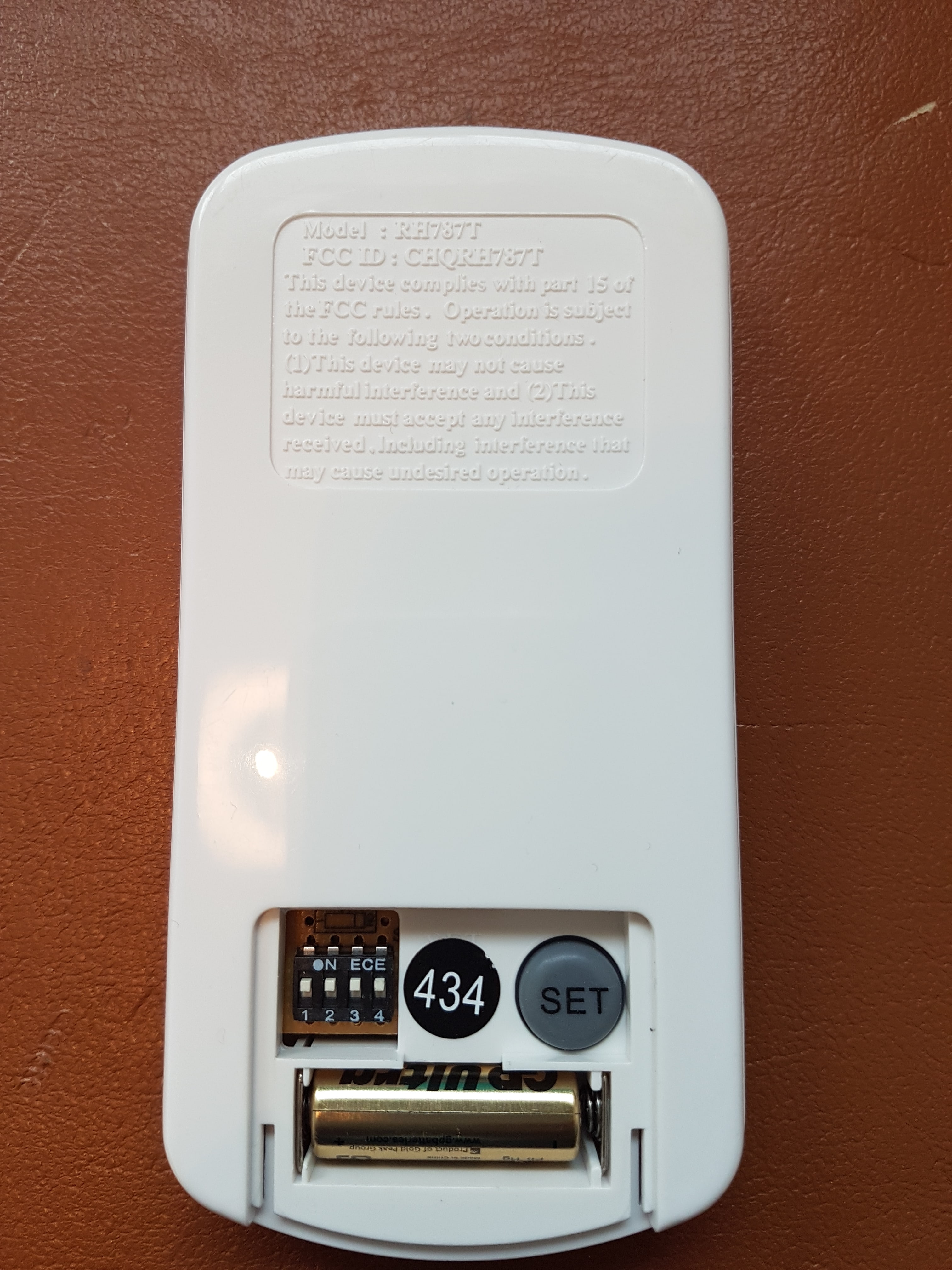
Any device that contained electronics capable of emitting RF energy by radiation, conduction, or other means above a certain threshold is required to be properly authorised and tested by the FCC in the USA and must display an FCC ID number. Looking at the back of our remote with the battery cover removed reveals the frequency (434Mhz), several dip switches as well as the FCC ID (figure 6). We can use this ID to search for documentation on fccid.io including manufacturer details, operating frequencies, photos, manuals and even the device submission covering letter, allowing us to learn plenty about the device.
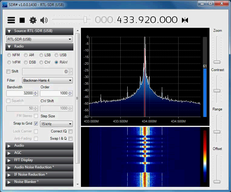
Follow this guide to set-up SDR# and once you have it running and tuned to your devices frequency, you should see a spike in the spectrum like this when a button is pressed:
Use SDR#'s built-in recording function to record the signal as an audio file.
Opening an audio recording of one of the signals in Audacity presents us with the following.
Once we have trimmed the white noise and zoomed in on the transmission, we see a series of twelve individual repeating signals with an interval of c12,000 microseconds.
Zooming in further to one of these signals shows us the individual bits being transmitted along with their transmission periods using the time index as a measurement.
This screenshot reveals a signal of: [1, 0, 1, 1, 0, 1, 1, 0, 1, 1, 0, 1, 1, 0, 1, 1, 0, 0, 1, 0, 0, 1, 0, 0, 1, 0, 0, 1, 0, 1, 1, 0, 0, 1, 0, 0, 1, 0] with each bit being transmitted for approximately 350 microseconds. We can use this information to program the microcontroller to replay the signal. Our RF remote control is sending data packets that appear to be 38 bits long and (after looking at several different signals) contain a fairly obvious preamble code comprising roughly the first 18 bits.
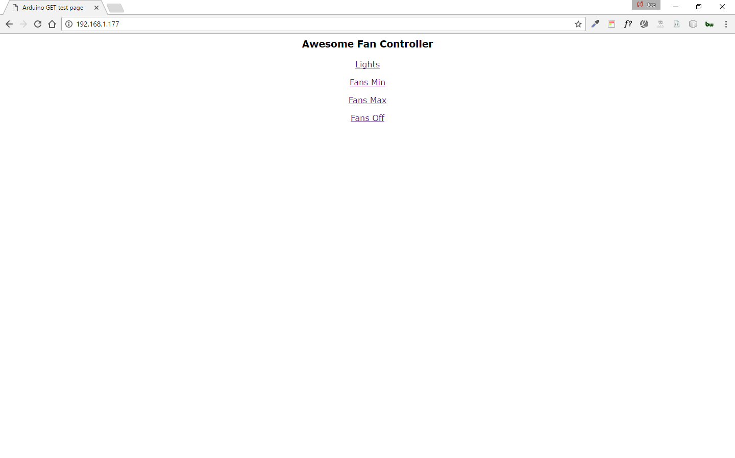
Next, we will create a simple web page served over LAN via an Arduino Ethernet shield module where the user will be able to click buttons to send HTTP requests to the board to trigger each transmission.
We include the ethernet library file and define a constant of 38 for the array length representing the signals to transmit as well as two floating point numbers representing periods of time in microseconds. The first is the period to transmit each bit of data for. The second represents the interval between sending packets. We also define two integers, a digital pin number (9) and the number of times to repeat each transmission (12). Four arrays are defined containing the 38-bit data packets to transmit. While the remote does have additional features, I have chosen just four signals due to storage constraints on the board and to avoid adding complexity with the additional of an SD card. Finally, we specify an IP address and port for the ethernet shield (192.168.1.177:80) to host our web server.
//Libraries
#include <SPI.h>
#include <Ethernet.h>
//RF data
#define BITS 38
int rfPin = 9;
int repeat = 12;
float period = 350;
float pausePeriod = 12000;
int lightCode [BITS] =  {1, 0, 1, 1, 0, 1, 1, 0, 1, 1, 0, 1, 1, 0, 1, 1, 0, 0, 1, 0, 0, 1, 0, 0, 1, 0, 0, 1, 0, 0, 1, 0, 0, 1, 0, 1, 1, 0};
int fanMinCode [BITS] = {1, 0, 1, 1, 0, 1, 1, 0, 1, 1, 0, 1, 1, 0, 1, 1, 0, 0, 1, 0, 0, 1, 0, 0, 1, 0, 1, 1, 0, 0, 1, 0, 0, 1, 0, 0, 1, 0};
int fanMaxCode [BITS] = {1, 0, 1, 1, 0, 1, 1, 0, 1, 1, 0, 1, 1, 0, 1, 1, 0, 0, 1, 0, 1, 1, 0, 0, 1, 0, 0, 1, 0, 0, 1, 0, 0, 1, 0, 0, 1, 0};
int fanOffCode [BITS] = {1, 0, 1, 1, 0, 1, 1, 0, 1, 1, 0, 1, 1, 0, 1, 1, 0, 0, 1, 0, 0, 1, 0, 0, 1, 0, 0, 1, 0, 0, 1, 0, 1, 1, 0, 0, 1, 0};
//WebServer data
byte mac[] = {0x90, 0xA2, 0xDA, 0x0D, 0x9C, 0x79};
IPAddress ip(192, 168, 1, 177);
EthernetServer server(80);
boolean reading = false;
String readString = "";
Our main setup function sets pin 9 on the board to an output pin and starts the HTTP server.
void setup() {
 pinMode(rfPin, OUTPUT);
 Serial.begin(9600);
 Ethernet.begin(mac, ip);
 server.begin();
 Serial.print("Server is at IP: ");
 Serial.println(Ethernet.localIP());
}
The main loop of the sketch checks if a client to connected to the server and reads the client request. If the client requested the home page directly, we render an HTML page containing control buttons. If the request contains a '?' character, it means a button has been pressed and is interpreted as a trigger action. The request header is checked for a number between 1 and 4 to determine which action to take and the appropriate packet array is passed to the sendRF function for transmission.
void loop() {
  EthernetClient client = server.available();
  if (client) {
    while (client.connected()) {
      if (client.available()) {
        char c = client.read();

        if (readString.length() < 100) {
          readString += c;
        }

        if (c == '\n') {
          Serial.println(readString); //print to serial monitor for debuging

          if (readString.indexOf('?') >= 0) { //don't send new page
            client.println("HTTP/1.1 204 Awesome Fan Controller\r\n\r\n");
          }
          else {
            client.println("HTTP/1.1 200 OK"); //send new page
            client.println("Content-Type: text/html");
            client.println();

            client.println("<HTML>");
            client.println("<HEAD>");
            client.println("<TITLE>Awesome Fan Controller</TITLE>");
            client.println("</HEAD>");
            client.println("<BODY style='font-family:verdana;'>");

            client.print("<center><h3>Awesome Fan Controller</h3>");
            client.print("<a href='/?1'>Lights</a>");
            client.print("<a href='/?2'>Fans Min</a>");
            client.print("<a href='/?3'>Fans Max</a>");
            client.print("<a href='/?4'>Fans Off</a>");
            client.print("</center>");

            client.println("</BODY>");
            client.println("</HTML>");
          }

          delay(1);
          client.stop();

          if (readString.indexOf("/?1") > 0) //checks for lights
          {
            sendRF(lightCode);
            Serial.println("Lights");
          }
          if (readString.indexOf("/?2") > 0) //checks for min
          {
            sendRF(fanMinCode);
            Serial.println("Fans min");
          }
          if (readString.indexOf("/?3") > 0) //checks for max
          {
            sendRF(fanMaxCode);
            Serial.println("Fans max");
          }
          if (readString.indexOf("/?4") > 0) //checks for off
          {
            sendRF(fanOffCode);
            Serial.println("Fans off");
          }

          readString = "";

        }
      }
    }
  }
}
Last but not least, we define a function to transmit the data packet which is passed as an argument. The function loops through each bit in the array and sets the digital output pin 9 high/low for the signal time and repeats the entire signal twelve times.
void sendRF(int code []) {
  for (int i = 0; i < repeat; i++) {
    for (int j = 0; j < BITS; j++) {
      if (code[j] == 0) {
        digitalWrite(rfPin, LOW);
      }
      else {
        digitalWrite(rfPin, HIGH);
      }
      delayMicroseconds(period);
    }
    delayMicroseconds(pausePeriod);
  }
}
It works!
https://github.com/samyk for the inspiration https://www.youtube.com/watch?v=blpycY5JCm0 for the tips My girlfriend for my constant stealing of the remote control and random light/fan shows!
