Ceramic/glass/metal kiln PID controller based on Arduino IDE and ESP32-Wrover board.
This is still work in progress, but since of release v0.7 (2019.09.24) it's fully functional. Just needs some more polishing.
- Interface accessible both from LCD screen and WWW Webpage
- Unlimited (limited only by storage) temperature programs number, program file size limited to 10KiB (but this is artificial limit - can be extended)
- Internal ESP SPIFFS storage for programs, data, logs, configuration (perhaps later SD - but I'm not sure yet)
- Local preferences on disk, editable with Web interface
- Online monitoring, program management, editing, graphs and kiln control
- Build in clock synchronised with NTP servers (if Internet connected)
- Safety features build in (temperature run out protection, probe failure, SSR failure, kiln insulation failure)
- Online PIDKiln firmware upgrade with web interface
- ...simply cool and cheap (comparing to commercially available products) all in one solution
- ESP32-Wrover board (I've used TTGO with MicroSD)
- MAX31855 breakout board
- K-type thermocouple
- DC->AC solid state relay
Kind of optional, but recommended:
- 128x65 dot matrix LCD 12864B v2
- Rotary encoder with button
Optional:
- DC/AC secondary relay - like SLA-05VDC-SL-C (240V/30A) mechanical relay
- Additional MAX31855 board with K-type thermocouple for housing temperature measuring
- Coil power meter - 30A/1V. This is contact less power meter that generates small current when energy flows inside it's coil. Mine already had burden resistor - so on output it produces -1V to 1V, proportionally it's coil rated for 30A. We just need to measure it to know how much juice flows to the heater.
- Perhaps a kiln :)
Total expenses for this set should be around 30-40$
-
ESP32-Wrover board: 11-14$ if exactly like mine, but other ESP32-Wrover you can bought for 6$+
-
MAX31855 board: ~2$
-
K-type thermocouple: 1$-10$ - depending on max temperature it can withstand
-
LCD 12864B: ~5$
-
Encoder: 1$
-
SSR: 4$ + 4$ for radiator
-
Mechanical relay EMR SLA-05VDC-SL-C (Songle): 3$
I've already used "kind of" controller made on Linux server and cron procedures, and it was ok.. for a while. Then I bought cheap Chinese controller PC410, just to find out, it is missing most of required stuff (that original PC410 should have), and I already was accustom to be able to see everything over Internet. So I've made few attempts with Arduino - it was fine, but since I need remote access - ESP will be much better choice. I've started to work on ESP8266, but being afraid that I will be lacking some GPIOs - I've moved to ESP32. And since price difference is negligible, this is the platform of choice for this project. It is also beneficial, because it has build in flash memory, that I can use for all required data - without need of connecting additional SD cards. Since I had ESP-Wrover (not ESP32-Wroom), I've also utilised it's PSRAM - so you also need to have one with it.
MAX31855 comparing to more available MAX6675, is better choice since it allow us to work up to 1350C and it has 3,3V logic.
LC12864B is perhaps not the best choice, but I simply had this one already (I've used if before for my 3D printer). Perhaps later I'll change it. Problem with this LCD is that it has 5V logic. Sometimes it works on 3,3V (depending on version), in my case it does. But since it's one way communication (only MISO) hooking it up to 5V for both logic and back light works and does not crash my board. Clean solution would be to use logic voltage translator (there is plenty of them for 1$).
Relays - Main relay is SSR (Solid State Relay) type. It's because we need to switch it fast and often - SSR can do it, but it will get hot, so make sure you have good radiator. Also if you are going to use cheap Chinese knock offs, make sure it's rated twice the output current of your heater(s). All relays may fail, and they may fail in closed (conductive) state. Because of it, I've also implemented second stage EMR (Electromechanical Relay) relay in case of SSR failure. It's mechanical, so it won't get hot too much. This will allow to turn off the kiln, in case of SSR failure, with EMR (and other way around too). This additional relay (SLA-05VDC-SL-C) is optional.
Initially for kiln housing temperature readout I wanted to use thermistors, but since I've already had MAX31855 connected (and it costs 2$), using additional one requires only 1 new GPIO on ESP. Without hassle to provide reference voltage etc. Low temperature thermocouples are also darn cheap.
LCD
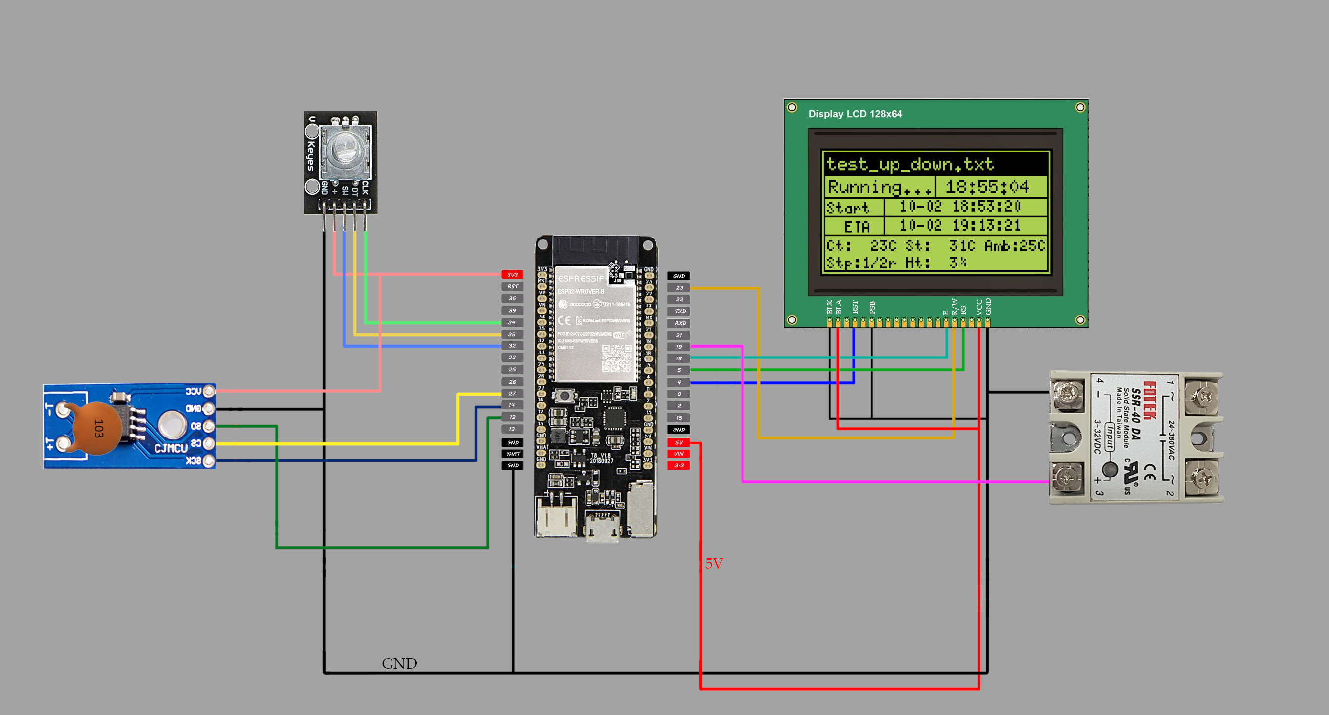
Connected to one of three SPI on ESP32 - called VSPI (MOSI-23, MISO-19, CLK-18, CS-5)
| ESP32 | LCD |
|---|---|
| +3.3V | BLA (this can be also +5V if you wish) |
| GND | BLK |
| 4 | RST |
| GND | PSB |
| +5V | VCC (This should be - for ESP sake - 3,3V, but my LCD doesn't work with lower voltage. Try first with 3,3V) |
| GND | GND |
| 5 | RS |
| 18 | E |
| 23 | R/W |
Encoder
| ESP32 | Encoder |
|---|---|
| +3.3V | 5V/VCC |
| GND | GND |
| 32 | Key |
| 34 | S2 |
| 35 | S1 |
MAX31855
Connected to one of three SPI on ESP32 - called HSPI (MOSI-13, MISO-12, CLK-14) CS-15/27
| EPS32 | MAX31855 A |
|---|---|
| +3.3V | VCC |
| GND | GND |
| 12 | SO/DO (slave output/data output) |
| 14 | SCK (clock) |
| 27 | CS (chip select) |
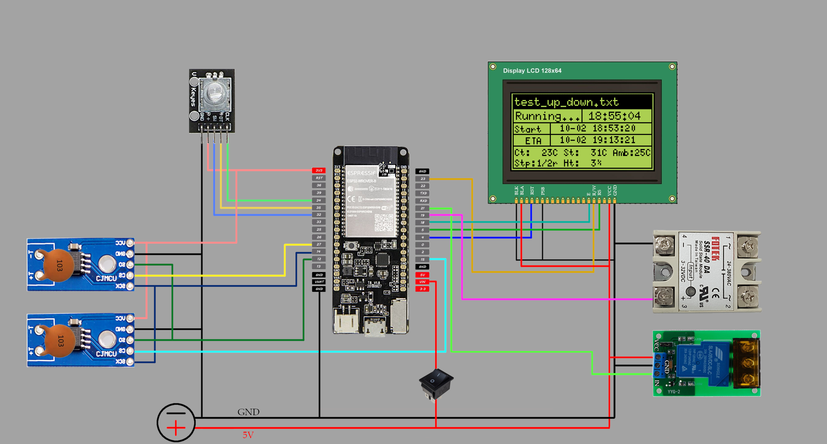
| EPS32 | MAX31855 B |
|---|---|
| +3.3V | VCC |
| GND | GND |
| 12 | SO/DO (slave output/data output) |
| 14 | SCK (clock) |
| 15 | CS (chip select) |
Relays
| ESP32 | SSR |
|---|---|
| GND | GND |
| 19** | IN |
| ESP32 | EMR (SLA-05VDC-SL-C) |
|---|---|
| GND | GND |
| 21 | IN |
| 5-48V* | VCC |
(*) Do not connect 5V from ESP - use external source. This can be any 5V-48V power supply with around 1W power. (**) For additional SSR relay (works simultaneously with first one) use PIN 22 - see documentation for explanation
Power meter
See the documentation for detailed instruction.
| ESP | 30A/1V |
|---|---|
| 3,3V | 3,3V |
| GND | GND |
| 33 | most outside mini jack connector |
Alarm
This ALARM_PIN goes HIGH when program ABORT is called (somethings wrong, or user triggered). You can connect this pin to buzzer or small relay to trigger some other action on failure.
| ESP | Relay/Buzzer |
|---|---|
| GND | GND |
| 26 | +3,3V |
Minimal configuration of PIDKiln
Standard configuration of PIDKiln
Preferably you should power your PIDKiln device with regulated 5V. This way you can power ESP32 board through VIN (do not use VIN and USB at once!) pin and use 5V to directly power EMR relay (around 185mA) and LCD backlight (depends of brightness). You could power board with just USB, but 5V output from my board (ESP32-Wrover TTGO with microsd) is too weak to handle EMR and LCD and most of other boards even do not have 5V out. You could also use VIN as 5V vout (this pin should be connected directly to USB 5V output) - but then you are limited by USB output and how much board traces can handle.
- Assembly hardware, as specified above.
- Clone git into the Arduino user programs directory (on Linux "/home/username/Arduino/").
- You have to already have installed ESP32 framework - if don't, do it now (https://github.com/espressif/arduino-esp32/blob/master/docs/arduino-ide/boards_manager.md).
- Don't forget about ESP32FS plugin (drop it to "/home/username/Arduino/tools")
- Install required additional libraries (all can be installed from Arduino IDE Library Manager): ESPAsyncWebServer,AsyncTCP, PID Library
- Install also my clone of Adafruit-MAX31855-library - this implements second HW SPI for ESP32
- Update (there is no other way to do it) libraries/ESPAsyncWebServer/src/WebResponseImpl.h variable TEMPLATE_PLACEHOLDER to '~'.
- For production use, disable serial debug in PIDKiln.ino - set it on false (''#define DEBUG false'')
- Compile and upload.
- Open data/etc/pidkiln.conf and edit your WiFi credentials (if you want to use) and, if you want, some additional parameters.
- Upload sketch data (from data directory) to ESP32 SPIFFS with help of ESP32FS plugin (in Arduino IDE go to Menu->Tools->ESP32 Sketch Data Upload).
- Most of the documentation you can find on PIDKiln github page - so please use it
- Some less formal updates information and step by step instructions will be on my webpage
Almost all, what I had in mind is done.. so not much to write here :) Perhaps...
- RTC clock for better timing and no Internet installations


