See too: Examples and tutorials found on the Internet for using the resources of the STM8
-
Note: This repository is no longer a fork of the original.
-
- To allow new forks and issue openings in case a bug is found
-----> Do not use the board without checking the relay LED problem. See below at "W1209 hardware (variation)"
- Note: On W1219 board, the LED is controlled independently of the relay.
- Apparently there is a bug in the compiler SDCC (v. 4.0.0), in case the display malfunctions when modifying the code:
-
- Add a 'long' variable in the first file (name in alphabetical order) *.c
a_file.c:
#include "a_file.h"
long foo;
-
Updates and new features have been added (Uses less program memory than the Arduino IDE).
-
- Navigation between files and references is easier than in the Arduino IDE.
-
- (apparently all functions working)
-
Makefile compilation mode, similar to the original way.
-
- (No more editing the Makefile file manually to modify source filenames).
-
Remote version (serial port emulated by timers) here.
-
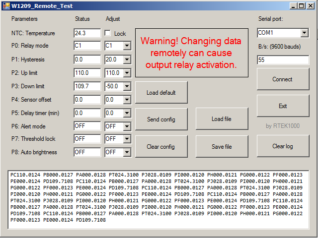
Windows app to manage settings:
-
Shows "HHH" or "LLL" on display if sensor fails, display flashing:
-
- If the sensor is disconnected, it shows "LLL".
-
- If the sensor is short circuited, it shows "HHH".
-
Code adaptation for Arduino IDE sketch.ino
-
Some bug fixes
-
Some functions added
-
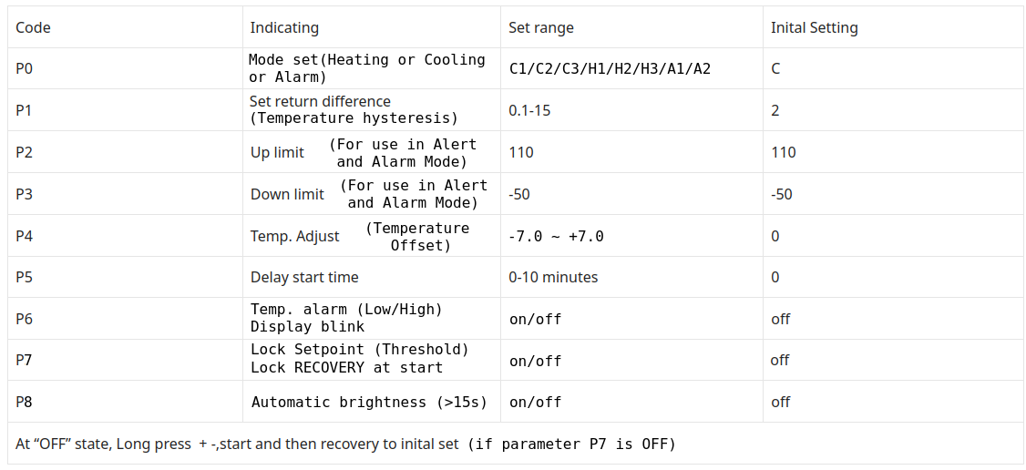
- Parameter P0: C1/C2/C3/H1/H2/H3/A1/A2
-
-
- C1: Cooler mode (hysteresis above Threshold)
-
-
-
- C2: Cooler mode (hysteresis below Threshold)
-
-
-
- C3: Cooler mode (hysteresis above and below Threshold)
-
-
-
- H1: Heater mode (hysteresis below Threshold)
-
-
-
- H2: Heater mode (hysteresis above Threshold)
-
-
-
- H3: Heater mode (hysteresis above and below Threshold)
-
-
-
- A1: Alarm mode (cause relay activation using the max. "P2" and min. parameters "P3")
-
-
-
-
- Temperature greater than the maximum value "P2": relay activated
-
-
-
-
-
- Temperature lower than the minimum value "P3": relay activated
-
-
-
-
- A2: Alarm mode (cause relay activation using the max. "P2" and min. parameters "P3")
-
-
-
-
- Temperature greater than the maximum value "P2": relay disabled
-
-
-
-
-
- Temperature lower than the minimum value "P3": relay disabled
-
-
-
- Parameter P1: Hysteresis (Degree hysteresis (°C) to toggle relay)
-
- Parameter P2: Up limit
-
-
- (Used in the alert indication; Activated in Parameter P6)
-
-
-
- (Used in Alarm mode Parameter P0: A1 and A2)
-
-
- Parameter P3: Down limit
-
-
- (Used in the alert indication; Activated in P6)
-
-
-
- (Used in Alarm mode Parameter P0: A1 and A2)
-
-
- Parameter P4: Temperature sensor offset
-
-
- (From -7.0 up to +7.0)
-
-
- Parameter P5: Delay time before activating the relay
-
-
- (From 0 to 10 minutes)
-
-
-
- (Does not affect relay deactivation, deactivation is immediate)
-
-
- Parameter P6: ON/OFF
-
-
- (Alert mode; Need setup Parameter P2 and P3; The display flashes when the temperature is outside the configured range.)
-
-
- Parameter P7: ON/OFF
-
-
- (Threshold value change access blocking)
-
-
-
- (Factory reset lockout with Up "+" and Down "-" keys)
-
-
- Parameter P8: ON/OFF
-
-
- (Automatic brightness reduction after 15 seconds)
-
-
Output status indication:
-
- Decimal point (DOT) right side off: Relay deactivated (contacts open)
-
- Decimal point (DOT) right side blinking: Relay deactivated (contacts open), but Waiting delay time programmed in Parameter P5
-
- Decimal point (DOT) right side on: Relay activated (contacts close)
-
- Factory reset:
-
-
- Set Parameter P7 in OFF
-
-
-
- Turn power supply Off
-
-
-
- Press and hold Up "+" and Down "-" keys
-
-
-
- Turn power supply On
-
-
-
- Wait for "rSt" to appear on the display
-
-
-
- Release all keys
-
-
-
- Wait for the current temperature to appear
-
-
Shows "HHH" or "LLL" on display if sensor fails, display flashing:
-
- If the sensor is disconnected, it shows "LLL"
-
- If the sensor is short circuited, it shows "HHH"
-
Troubleshoot:
-
- Microcontroller resetting: Try using a pull up resistor on the reset line
-
- Microcontroller no longer responds: High voltage return may have occurred through the relay LED
-
- The temperature does not correspond to the real: Try adjusting the offset Parameter P5 Try to replace the sensor Test using a resistor of NTC equivalent value for 25°C (10k) Try modifying the lookup table corresponding to the sensor
-
- Display flickering: Disconnect STlink programmer from SWIM port (next to display)
-
Note for Arduino IDE and Sduino core: Track the size of the code when uploading, The maximum I got was 93%
-
- (Sketch uses 7589 bytes (92%))
-
- (Bytes written: 8136)
-
- (Maximum is 8192 bytes)
-
Sduino core:
-
- Select STM8S Board / STM8S103F3 Breadout Board
-
- Programmer ST-link/V2
-
- Connect STlink: GND/SWIM/RST
-
ST-Link V2 Programming Example on Linux (check Bin folder):
-
- stm8flash -c stlinkv2 -p stm8s003?3 -w W1209-firmware-Arduino-table_R2_5k1_NTC_10k_B3950.hex
-
-
- Determine FLASH area
-
-
-
- STLink: v2, JTAG: v40, SWIM: v7, VID: 8304, PID: 4837
-
-
-
- Due to its file extension (or lack thereof), "W1209-firmware-Arduino-table_R2_5k1_NTC_10k_B3950.hex" is considered as INTEL HEX format!
-
-
-
- 8136 bytes at 0x8000... OK
-
-
-
- Bytes written: 8136
-
-
References:
-
-
Note:
-
- To enter the main configuration parameters menu:
-
-
- Press the SET key for a long time (for more than 5 seconds).
-
-
-
- Press the "+" or "-" keys to toggle between parameters "P0" through "P8".
-
-
-
- Short press SET key to enter the parameter.
-
-
-
-
- Press the "+" or "-" keys to change values.
-
-
-
- Long press SET key or no press (for 10 seconds), confirm and return automatically.
-
Note: Added delay for debounce, for fast increment hold key down.
There is an error in the electronic circuit that can kill the microcontroller, make the modification as soon as possible. Avoid using the board without modifying it. See here.

-
Other details can be seen in this post.
-
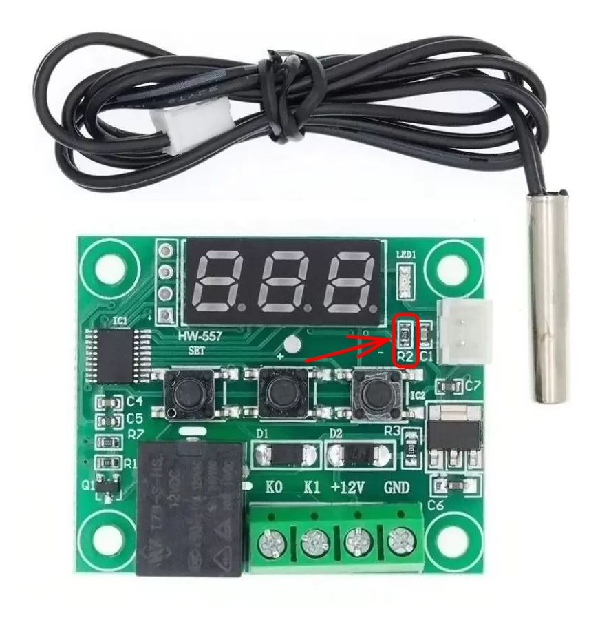
The generic schematic diagram shows the value of 20K ohms for R2:

-
R2 resistor: Some boards have a resistor value of 20k, others may have different values such as 5.1k, check the table in the adc.c file, if your board has a different value for R2 or for the sensor, it may be necessary to change the table rawADC[ ]:

-
To generate a custom lookup table for a different sensor, you can use this tool:
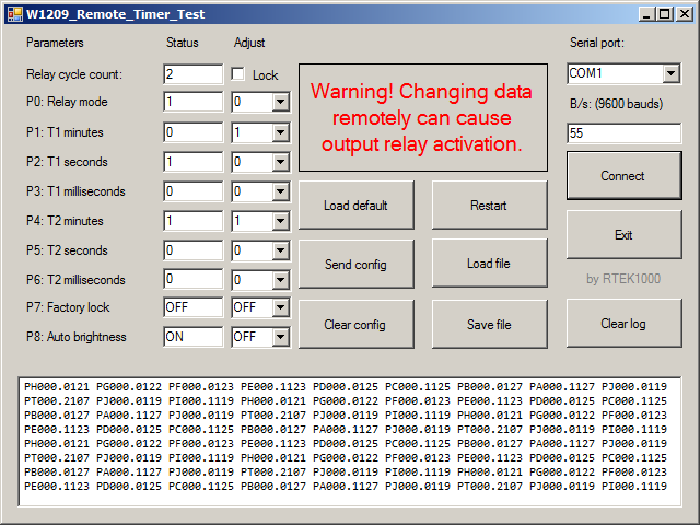
Firmware to use the W1209 as a programmable timer: here
- There are 6 modes of operation (Looped or non-looped).
- Maximum time about 1000 minutes (about 16 hours and 40 minutes).
- Two-step timing (Times separated in minutes, seconds and milliseconds).
- Display automatically shows the most significant digits.
- Sensor input operating as a button.
- Remote Control (App Windows for tests).
- Note: This library is distributed in the hope that it will be useful, but WITHOUT ANY WARRANTY; without even the implied warranty of MERCHANTABILITY or FITNESS FOR A PARTICULAR PURPOSE. See the GNU Lesser General Public License for more details.
-
w1209-firmware
-
- The functional equivalent to the original firmware of "Digital Thermostat Module Model XH-W1209".
-
- The F.A.Q. page is available at https://github.com/mister-grumbler/w1209-firmware/wiki/FAQ
-
- Look at the list of issues to have an idea of what needs to be done for the initial release. https://github.com/mister-grumbler/w1209-firmware/issues


