References:
- Based on Plippo's discovery of WMI methods used for screenpad backlight (ref), which is incorporated as part of the linux asus-wmi-screenpad repository:
-
// include/linux/platform_data/x86/asus-wmi.h#L54-60
// + asus-wmi-screenpad/inc/asus-wmi.h#L5-6
  54  | /* Backlight and Brightness */
  55  | #define ASUS_WMI_DEVID_ALS_ENABLE       0x00050001
  56  | #define ASUS_WMI_DEVID_BACKLIGHT        0x00050011
  57  | #define ASUS_WMI_DEVID_BRIGHTNESS       0x00050012
  58  | #define ASUS_WMI_DEVID_KBD_BACKLIGHT    0x00050021
  59  | #define ASUS_WMI_DEVID_LIGHT_SENSOR     0x00050022
  60  | #define ASUS_WMI_DEVID_LIGHTBAR         0x00050025
+ 61  | #define ASUS_WMI_DEVID_SCREENPAD        0x00050031
+ 62  | #define ASUS_WMI_DEVID_SCREENPAD_LIGHT  0x00050032
-
- See SSDT-SPLC.dsl (and issue Screenpad Plus Backlight Control #6) for implementation notes:
-
External (\_SB.ATKD.WMNB, MethodObj)
// Sets the screenpad plus backlight intensity,
// where 'xx' is a hex value between 0x00 and 0xFF.
\_SB.ATKD.WMNB(0x0, 0x53564544, /*b32000500xx000000*/)
//                  ^--Arg1--^     ^-----Arg2-----^
//                                 ^-IIA0-^^-IIA1-^
// Disables screenpad plus until next backlight change.
\_SB.ATKD.WMNB(0x0, 0x53564544, /*b3100050000000000*/)
//                  ^--Arg1--^     ^-----Arg2-----^
//                                 ^-IIA0-^^-IIA1-^
-
// Reference: docs/resources/firmware/UX481FL/DSDT.dsl
        // \_SB.ATKD.WMNB
54953 | Method (WMNB, 3, Serialized)
54954 | {
54955 |     CreateDWordField (Arg2, Zero, IIA0)
54956 |     CreateDWordField (Arg2, 0x04, IIA1)
54957 |     Local0 = (Arg1 & 0xFFFFFFFF)
...
55362 |     If ((Local0 == 0x53564544))
55363 |     {
...
55524 |         Name (TMBF, Buffer (0x02)
55525 |         {
55526 |             0x00, 0x00
55527 |         })
55528 |         If ((IIA0 == 0x00050031))
55529 |         {
55530 |             TMBF [Zero] = Zero
55531 |             Local0 = ^^PCI0.LPCB.EC0.REBC (0x12, 0x02)
55532 |             Local1 = DerefOf (Local0 [Zero])
55533 |             If ((IIA1 == One))
55534 |             {
55535 |                 Local1 &= 0xFD
55536 |             }
55537 |             Else
55538 |             {
55539 |                 Local1 |= 0x02
55540 |             }
55541 |
55542 |             TMBF [One] = Local1
55543 |             Return (^^PCI0.LPCB.EC0.WEBC (0x13, 0x02, TMBF))
55544 |             Return (Zero)
55545 |         }
55546 |
55547 |         If ((IIA0 == 0x00050032))
55548 |         {
55549 |             TMBF [One] = IIA1 /* \_SB_.ATKD.WMNB.IIA1 */
55550 |             TMBF [Zero] = One
55551 |             Return (^^PCI0.LPCB.EC0.WEBC (0x13, 0x02, TMBF))
55552 |             Return (Zero)
55553 |         }
55554 |
55555 |         If ((IIA0 == 0x00050035))
55556 |         {
55557 |             TMBF [Zero] = Zero
55558 |             Local0 = ^^PCI0.LPCB.EC0.REBC (0x12, 0x02)
55559 |             Local1 = DerefOf (Local0 [Zero])
55560 |             If ((IIA1 == Zero))
55561 |             {
55562 |                 Local1 &= 0xF7
55563 |             }
55564 |             ElseIf ((IIA1 == One))
55565 |             {
55566 |                 Local1 |= 0x08
55567 |             }
55568 |
55569 |             TMBF [One] = Local1
55570 |             Return (^^PCI0.LPCB.EC0.WEBC (0x13, 0x02, TMBF))
55571 |             Return (Zero)
55572 | }References:
- linuxhw EDID repo:
MFG Model Name Res Inch Made ID BOE BOE087F HF NV126B5M-N41 1920 x 515 12.6 2019 46E74341751E
edid-decode (hex):

00 ff ff ff ff ff ff 00 09 e5 7f 08 00 00 00 00
01 1d 01 04 a5 1f 08 78 02 d2 2d 93 51 57 8d 28
18 4e 52 00 00 00 01 01 01 01 01 01 01 01 01 01
01 01 01 01 01 01 94 1b 80 a0 70 03 32 20 30 20
55 00 35 53 10 00 00 1a 12 16 80 a0 70 03 32 20
30 20 55 00 35 53 10 00 00 1a 00 00 00 fe 00 42
4f 45 20 48 46 0a 20 20 20 20 20 20 00 00 00 fe
00 4e 56 31 32 36 42 35 4d 2d 4e 34 31 0a 00 ed

----------------

Block 0, Base EDID:
  EDID Structure Version & Revision: 1.4
  Vendor & Product Identification:
    Manufacturer: BOE
    Model: 2175
    Made in: week 1 of 2019
  Basic Display Parameters & Features:
    Digital display
    Bits per primary color channel: 8
    DisplayPort interface
    Maximum image size: 31 cm x 8 cm
    Gamma: 2.20
    Supported color formats: RGB 4:4:4
    First detailed timing includes the native pixel format and preferred refresh rate
  Color Characteristics:
    Red  : 0.5771, 0.3173
    Green: 0.3398, 0.5527
    Blue : 0.1562, 0.0957
    White: 0.3076, 0.3212
  Established Timings I & II: none
  Standard Timings: none
  Detailed Timing Descriptors:
    DTD 1:  1920x515    60.074881 Hz 384:103   33.942 kHz     70.600000 MHz (309 mm x 83 mm)
                 Hfront   48 Hsync  32 Hback   80 Hpol P
                 Vfront    5 Vsync   5 Vback   40 Vpol N
    DTD 2:  1920x515    48.076923 Hz 384:103   27.163 kHz     56.500000 MHz (309 mm x 83 mm)
                 Hfront   48 Hsync  32 Hback   80 Hpol P
                 Vfront    5 Vsync   5 Vback   40 Vpol N
    Alphanumeric Data String: 'BOE HF'
    Alphanumeric Data String: 'NV126B5M-N41'
Checksum: 0xed

----------------

Warnings:

Block 0, Base EDID:
  Basic Display Parameters & Features: Dubious maximum image size (31x8 is smaller than 10x10 cm).

Failures:

Block 0, Base EDID:
  Missing Display Product Name.

EDID conformity: FAIL
References:
- Schematic: Asus ZenBook Duo UX481FL Rev 2.0.pdf
- Boardview: UX481FL-W25Q128.BIN
Datasheets:
- BOE NV126B5M-N41:
Parts:
| Item | Image |
|---|---|
| Asus Screen module blue touch screenpad FHD 12 SKU: MODULESCREENPADUX481BLUEFHDP/N: 90NB0P61-R20010EDP Cable reference: 1422-03ER0AS |
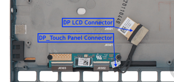 |
| Asus Touch controller card for UX481FLY SKU: TOUCHCONTBDUX481P/N: 90NB0P60-R10020Model: 60NB0P60-TP1020 |
 |
| Pin | Signal | PCH GPIO | DP LCD Connector (J4501) | Description |
|---|---|---|---|---|
| AC6 | DDI1_AUX_P | DP_AUXP_C | DP1 Auxiliary Channel (AUX_CH) | |
| AC7 | DDI1_AUX# | DP_AUXP_C | DP1 Auxiliary Channel (AUX_CH) | |
| AL5 | DDI1_TXN_0 | DDI1_TXN0_C | DP1 differential negative input (ML_Lane 0) | |
| AL6 | DDI1_TXP_0 | DDI1_TXP0_C | DP1 differential positive input (ML_Lane 0) | |
| AJ5 | DDI1_TXN_1 | DDI1_TXN1_C | DP1 differential negative input (ML_Lane 1) | |
| AJ6 | DDI1_TXP_1 | DDI1_TXP1_C | DP1 differential positive input (ML_Lane 1) | |
| CN6 | DDPB_HPD0 | GPP_E13 | DP_HPD_PCH_C | Also known as SPI1_MOSI. This handles sending SPI1 touchscreen serial input data to the PCH. |
| CC8 | DDPB_SCL_PCH | GPP_E18 | Also known as DDP1_CTRLCLK. Handles control clock data for Display Port C. |
|
| CC9 | DDPB_SDA_PCH | GPP_E19 | Also known as DDP1_CTRLDATA (used as TBT_LSX). Handles DDP1 I2C / TBT_LSX0 pins VCC configuration. • 0 = DDP1 I2C / TBT_LSX0 pins at 1.8V• 1 = DDP1 I2C / TBT_LSX0 pins at 3.3V |
| Pin | Signal | PCH GPIO | EC IT8225 GPIO | CPU (U0301A) | Description |
|---|---|---|---|---|---|
| 1 | CABC_DP_EN | GPJ7 (CABC_EN) | |||
| 2 | (GND) | ||||
| 3 | DP_TXN1_C | DDI1_TXN_1 | [^] | ||
| 4 | DP_TXP1_C | DDI1_TXP_1 | [^] | ||
| 5 | (GND) | ||||
| 6 | DP_TXN0_C | DDI1_TXN_0 | [^] | ||
| 7 | DP_TXP0_C | DDI1_TXP_0 | [^] | ||
| 8 | (GND) | ||||
| 9 | DP_AUXP_C | DDI1_AUX_P | [^] | ||
| 10 | DP_AUXN_C | DDI1_AUX# | [^] | ||
| 11 | (GND) | ||||
| 12 | (GND) | ||||
| 13 | - | ||||
| 14 | +3VS_DP | ||||
| 15 | +3VS_DP | ||||
| 16 | - | ||||
| 17 | DP_HPD_PCH_C | GPP_E13 (DDPB_HPD0) | GPF4 (DP_HPD#) | [^] | |
| 18 | DP_BLEN_C | GPB2 (DP_BL_EN) | |||
| 19 | DP_PWM_C | GPA7 (DP_PWM) | |||
| 20 | - | ||||
| 21 | AC_BAT_SYS_DP | ||||
| 22 | AC_BAT_SYS_DP | ||||
| 23 | - | ||||
| 24 | - | ||||
| 25 | +3VS_TP | ||||
| 26 | (GND) | ||||
| 27 | DP_TP_Report_SW | ||||
| 28 | I2C3_SCL_TCH_PNL | GPP_H7 | I2C link 3 serial clock line (touchscreen). | ||
| 29 | I2C3_SDA_TCH_PNL | GPP_H6 | I2C link 3 data clock line (touchscreen). | ||
| 30 | TPanel_INT#_2ND | GPP_B18 | Also known as GSPIO_MOSI. This is a pin-up strap that toggles 'No Reboot' mode. • 0 = Disable “No Reboot” mode. (Default)• 1 = Enable “No Reboot” mode (PCH will disable the TCO Timer system reboot feature). |
||
| 31 | GND1 | ||||
| 32 | GND2 | ||||
| 33 | GND3 | ||||
| 34 | GND4 |
Datasheets:
- Intel Comet Lake Processors:
- Intel 495 Series Chipset:
- BOE NV126B5M-N41: