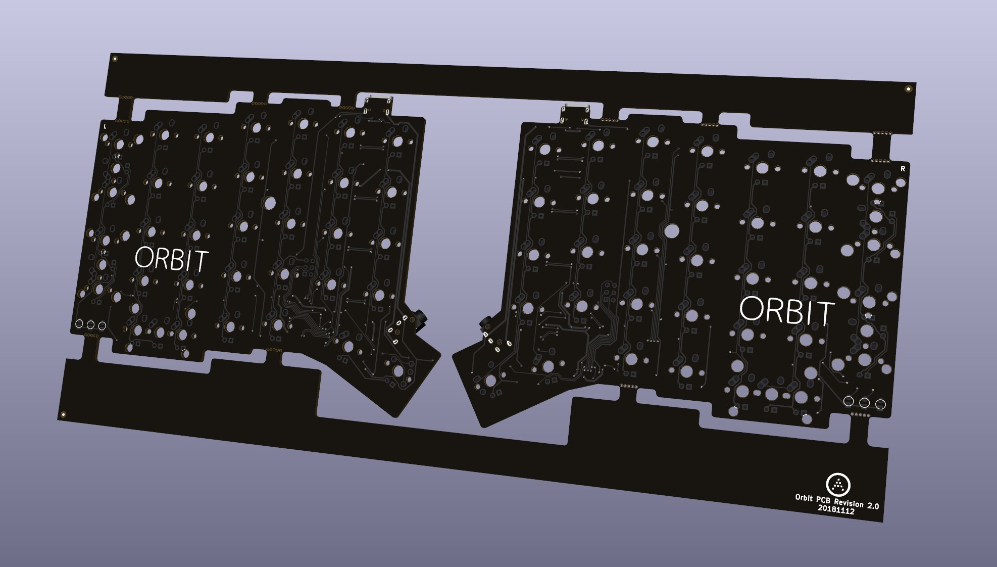
A split ergonomic keyboard for all
In light of recent claims that I am 100% liable for any of my open source PCBs, I am adding this disclaimer.
I provide these PCBs as a reference for designing keyboard PCBs. Using them within your projects will require a will to do research of one's own and to learn the workings of them, potentially fixing issues if they exist.
I provide these PCBs without liability and without any guarantees regarding functionality, as expressed in the licenses under which these PCBs are licensed.
- Ergonomic layout based on the crkbd
- All on-board components; no separate controller board
- USB Type-C and in-switch backlight
- Alps SKCL/M and MX compatibility
- Built-in overcurrent, reverse voltage, and ESD protection.
- Pre-panelized in a single PCB file for easy production
- Keyboard-Layout-Editor data is available here.
- This keyboard remains close to typical QWERTY layout in key positioning.
- Most keys remain in their typical locations, which allows easy migration from standard layout keyboards.
- Whether new to ergonomic layouts or already an avid adopter, Orbit will suit your needs.
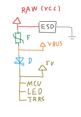
- The incoming power is handled as shown:

- VCC/Raw is the raw power fed through the USB connector. The ESD protection IC is bound to here.
- VBUS is "stable raw power" after being passed through a polyfuse. Used for upstream detection, for a downstream Schottky diode prevents flow from 5V into VBUS. In other words, VBUS is only at 5V when fed from upstream USB.
- 5V is the "stable power" after passing through a Schottky diode. Used for powering MCU, LEDs, and other split half. Power from the other half feeds here, for it has already been filtered on the other side.
- Measures are taken to isolate the LED, MCU, and split connection 5V as upstream as possible to prevent interference.
- Ground plane is limited to critical parts for aesthetic reasons.
- Top side of PCB is mostly covered with soldermask.
