-
Notifications
You must be signed in to change notification settings - Fork 4.8k
New issue
Have a question about this project? Sign up for a free GitHub account to open an issue and contact its maintainers and the community.
By clicking “Sign up for GitHub”, you agree to our terms of service and privacy statement. We’ll occasionally send you account related emails.
Already on GitHub? Sign in to your account
1 Channel Inching/Self-lockIing Mode WiFi Wireless Switch 5V/12V and Sonoff-Tasmota? #893
Comments
|
You can use Tasmota. |
|
From left to right: |
|
Thanks! |
|
Hi, my board does not have connected RX and TX to the chip, so I must used wires with needles and connect directly to the chip. TX and RX is 2nd and 3rd from to left corner. And be aware about changed 3,3 and gnd pin!!!!! First connect 3,3 and gnd and check without button presing if led go on. Fter that start with pressed button. Then press second button, to have both leds light on. Then you can flas with needles, I had so 70 trys, because my hand shaked a lot ;) P.S. I used autoclick with 20s delay to upload firmware ;) |
|
Related to @ionciubotaru must the occupancy look like this on my relay? (White): |
|
Eat the elephant by pieces. First locate 3,3 + GND. |
|
@tomasroud Now i have tested that what you are explaining. But i don't know how to come in flash mode. Can you tell me? EDIT: Now when i connect the 3v3 and GND no light flash on the Sonoff... |
|
Press one button nr. 1 or 2, try it and then connect to usb. If lights only 1 led, press next button till both of leds light. Tell me, how it works. P.S. When you connect 3,3 and GND, it will be too at bottom two pins on block nr. 3 |
|
I use the same arrangement as at the beginning. In the beginning lights still lit. For some reason now lights nothing more when I connect via USB. I do not think this is broken. Can be connected where else GND RX TX and 3v3? With the normal build in USB of the Sonoff it works perfectly. So the Board is not broken |
|
3,3 and GND are bottom 2 pins in block nr. 3, try it there, if the board will live. Try with ohmmetter that these pins are same as 3,3V and GND. |
|
@tomasroud No light on the block 3 :( |
|
USB adapter can be broken on TX or RX, on 3,3 and GND probably not. So it must be OK. |
|
|
|
Idk if this is stupid but i connected 3,3v on board voltage and GND, RX, TX like this picture |
|
The board lives, that is cool, so, you should connect your USB adaptor to USB in pc in same time as btn. is pressed. Then both LEDs will light ... not flash, light still. OK? P.S. That error means TX or RX is not connected or board is not in fllashing mode (2 LEDs light still) |
|
You must flash with VCC and GND from USB in PINS only. I see you have connected main voltage, it is not possible to flash the device like that. Unplug micro USB voltage, connect voltage in pins and tell me, if you can set up both these pictures too. |
|
I'm not able to get in this light mode on picture 2 with VCC and GND connected :( |
|
Press btn1 when connected to USB and release. Then press btn 2. IT MUST STAY IN 2 LEDs light on. |
|
No it don't work. I think I have a Version of the Sonoff, that is not flash able :( |
|
I am wondered, but maybe it is possible. I am sorry, that I can not help you :( |
|
This is how flashing mode should look like: https://www.youtube.com/watch?v=E0WBoFCcnYY |
|
Thank you for the Video. I can access this mode like in the video but im not able to flash the sonoff. |
|
Got it finally working!!! |
|
Sucsesfull flashed this with SonOTA |
|
Yesssss also!!! but which device belongs in the configuration set? |
|
Hello everyone , i am totally new on git , this board is very useful for me and i want to use this board with my own android application . I would be great full if some can help me find the android sdk for this board . |
Have same problem. After soft-restart in webui, relay switch 1-0. |
|
hello, please can anyone help me, I have tried every possible combination of wires and button holds as I power on, I am using ESP easy, lol. The Sonoff device is a 1 channel inching type, the serial device is a DSD tech FT232 TTL. I have looked for pin outs for the serial device and can not find, I have tried with the jumper on the RTS and CTS pins and without. I have tried 5v and 3.3V jumpers, I do not think I fried anything yet but the serial board did get a bit hot at first. Everything still seems to light up and at least is not completely dead yet, not even sure which button to hold down so I have tried both seperately. Please see the picture showing 2 boards, I get flash failed every time, so it at least attempts to connect. Orange and yellow are TX and RX, Red is +, brown is ground. |
was your USB programmer obviously dead? Just wondering if I messed mine up, it is still seen by Windows, powers up, shows a TX light, but is not flashing the Sonoff inching device. |
Absolutely the same behavior. Any workaround? |
|
I wanted to reopen this (it can be immediately reclosed) JUST because I know of no other place to post this valuable information, and in my pursuit of the information I found no other place online where it is properly discussed!! Here is how to flash your PSF-B01. Use this flash boot method (press both buttons while powering it. Both LEDs need to come on. You can flash Tasmota now. Once booted, set it to module "1 channel (12)" in the included module list (no external template is needed). VERY IMPORTANT This will disable the "triple press" functionality that usually reboots ESP8266 into SmartConfig Mode. After that, you can select via the hardware button if you want inching or locking latch, and you are good to go! I hope this message saves someone A LOT of time. I took me quite a while to figure out why the module was going haywire. |
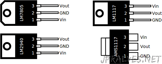
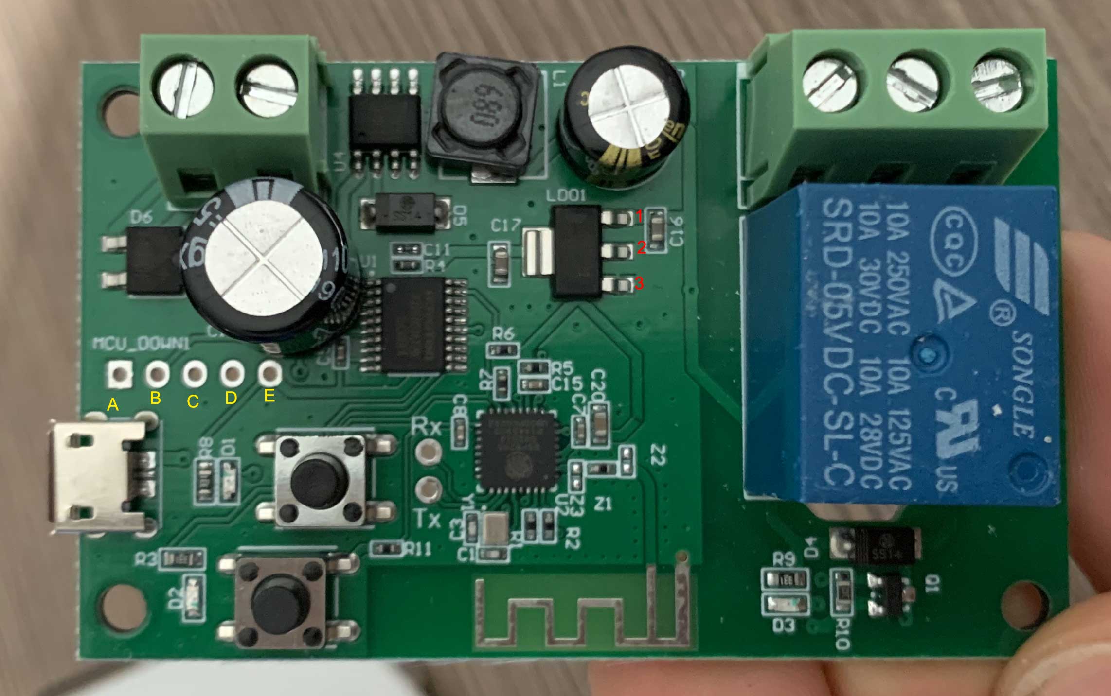
To teach a man to fish ... To fish for a man......(happy to save you the time) Ground is even easier to find--- it will also be one of the three LD01 legs. From the photo I'd bet its the closest to the bottom.. .and connecting to the ground plane. You can use your meter to find 3.3v between your now-known 3.3v pin on that device and one of the other two small legs. You can just connect the ground right onto that chip too (with your 3.3v FTDI. If you are using a 5 volt you'll want to connect the 5v to U4 instead). Highly recommend you verify your measurements match the pinout datasheet, just to double check yourself. Hope this helps!! You may already know, but you also need to get the ESP chip into boot mode, which may require grounding of some of the GPIOs. Try it by just using the GPIO0 button held during boot, first. If that doesnt work you may wnat to look up the pinout of the particual ESP you have on there and see what it needs. I have seen ones that ned more than GPIO0 ... like 15(?) also grounded at boot. It also depends what is wired to it on the board itself (I had to cut a trace and then repair it later to get it to flash). You shouldnt have much trouble finding this info out there in the web! Let us know if yo uneed more assist |
|
Well, 1= 5v, 2= 3.3v and 3= ground. This matches the pinout I posted above (but you are using numbers in reverse, nbd). With that said, I would be cautious about assuming anything about ABCDE. Not sure you are certain that one of those is not just "pulled high" by the ESP chip, or if it is actually tied to pin 2. Same for the 0v readings, is it connected to GPIO and just pulled low at the time you're measuring, or actually tied to ground? Cant be sure of that from what you tested so far What you would do to verify that is either--- break out a bagnifying glass and very carefully follow the traces from the pin #2. Does it go to A B C D or E? Yoiu could also flip your multimeter into continuity mode (it either makes a beep or reads 0ohms when both probes are touched together), make sure your board is unpowered, and probe pin 2. Do you get zero ohms to any of the letter pads? If so, and you can see a trace that goes direct between the two-- only then would I say you are good to use the letter pads. Otherwise, just tack a wire onto pin 2 for your 3.3v+ and pin 3 for your ground. Those we are certain about already! Though, A def seems like a ground pad. The square pad itself tells us that too. |
|
Ok. I set the multimeter to continuity mode. A= Gnd and E =3,3v? |
Where you ever able to get this board in flash mode? I for the life of me can't get it to boot in flash mode. I have tried the button hold down method, and when that didn't work I assumed they aren't connected to GIO0, so I tried grounding what I believe to be the GIO0 pin on the esp itself |
|
To the future person googling for this board using the previous mentioned numbering scheme Important: To fix flashing being unstable add a capacitor to 2,3 Hold down the button closest to the Rx/Tx when you boot up, Tada |
Thank you for making me gain valuable time! I installed HAA and currently using one of these as door electric strike relay |
|
Hi, can you help me? |
|
Please address this to the Tasmota Support Discord Chat. The chat is a better and more dynamic channel for helping you. Github issues are best used for Tasmota software feature requests and bug reporting. Troubleshooting and setup assistance is more effective using an interactive forum. Please check the Contributing Guideline and Policy and the Support Guide. Thanks. Support InformationSee Wiki for more information. |
|
|
Anyone figure out the solution to prevent the relay from switching on when performing a soft reset? I noticed that it also does this behavior when wifi disconnects, this is a big problem |
|
Secondary Pins of the relais don't have any connection. You have to connect any external power to com. This will be switched from NO to NC |
|
Hi, |
|
Just want to add some info since I have just flashed my board that is almost the same. My board does not show any LED when in flash mode. I press 1 button closest to the capacitor and then plug in the usb then let go the button. Unit is in flash mode with now LED on. then I just hold the TX and RX pins to the ESP chip RX TX and then it flashed. |
|
Flashed mine today, powered from USB keeping both button pressed. |
|
weird mine had no LED going on. and I know they work because when paring them initially it shows. |


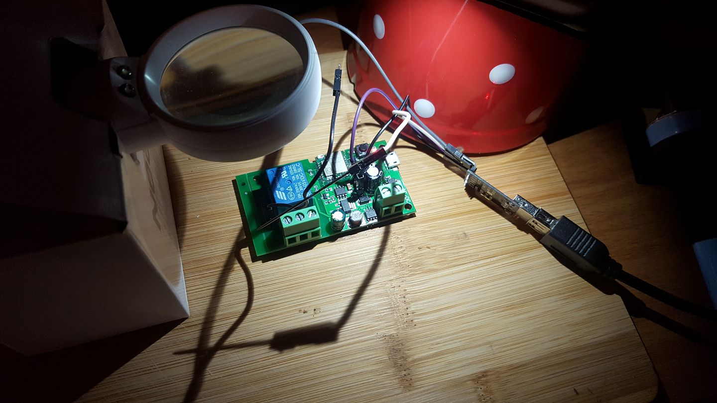
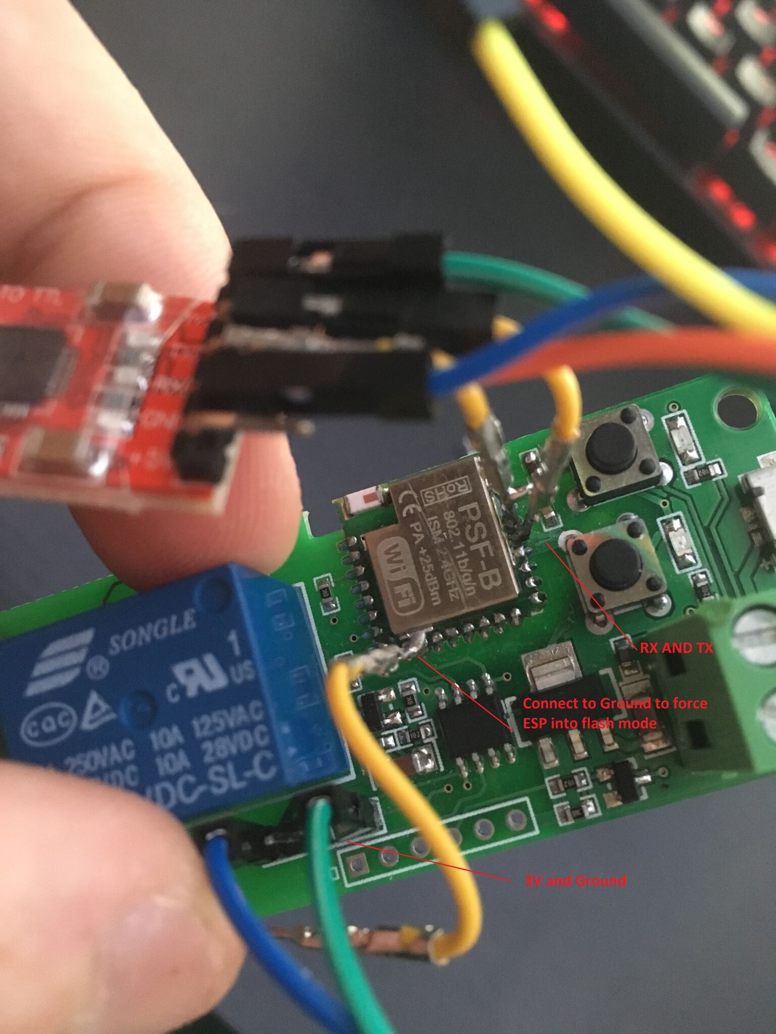
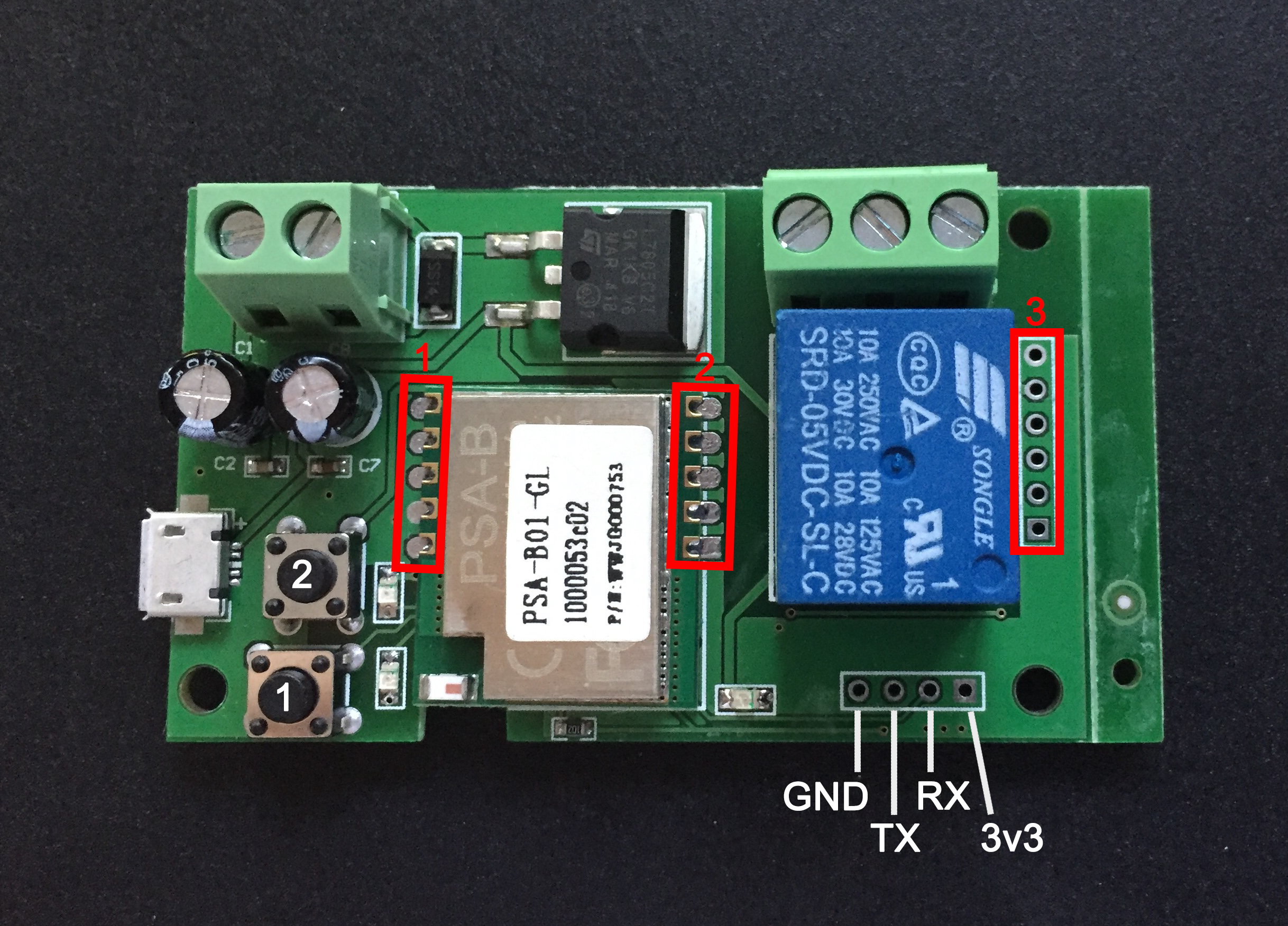


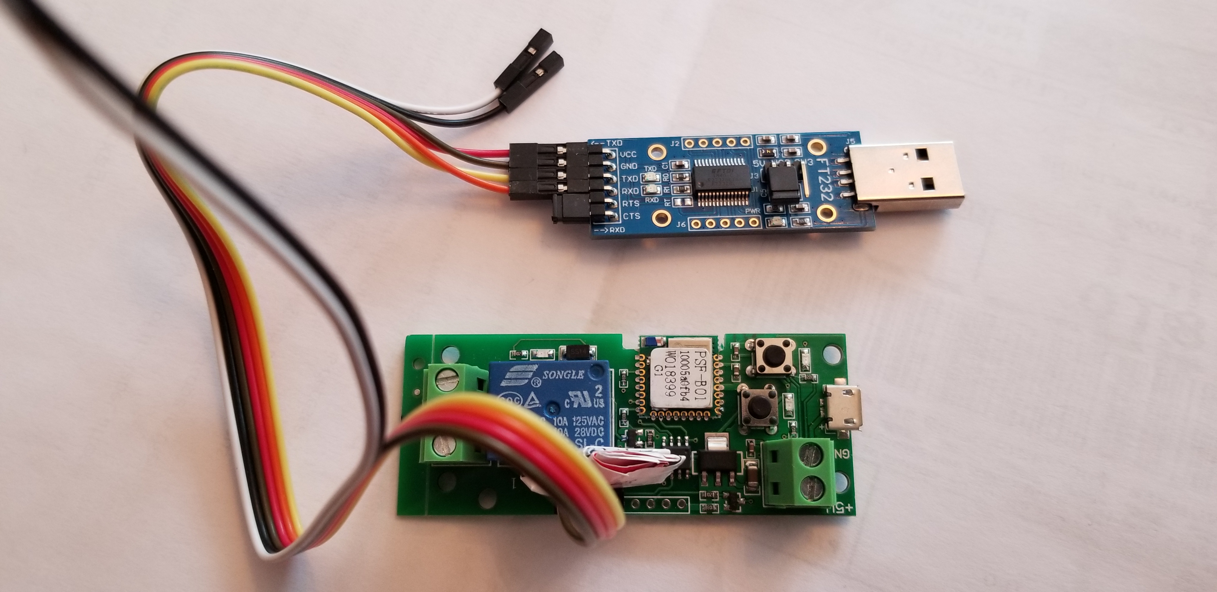


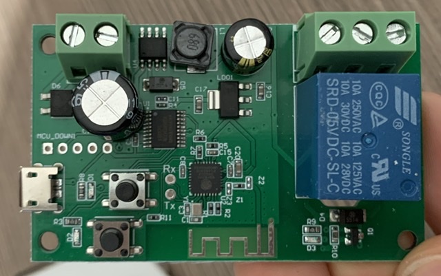



Hallo,
sorry i never posted anything on GitHub but I have a question and can't find a solution at this time. I'm a noob and like to control my Garage Door with Siri and Homebridge. My Garage Door needs a pulse to open/close.
I bought the "1 Channel Inching/Self-lockIing Mode WiFi Wireless Switch 5V/12V" from itead.cc and like to use it with the Sonoff-Tasmota Firmware to connect via plugin to Homebridge.
Pictures of the Relay:
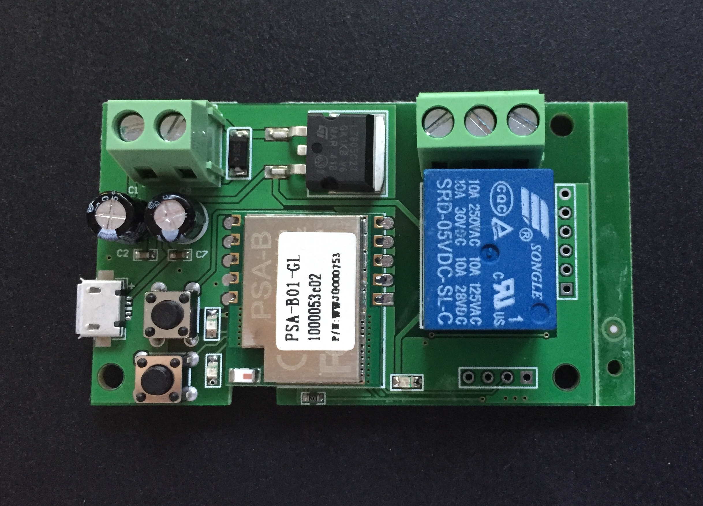

Is it possible to flash the Sonoff-Tasmota Firmware to this relay?
Where do i have to connect my USB adapter or can i just use the build in USB Port?
Where are the RX, TX, GIO Ports on this Relay?
I hope anybody can help me and sorry for my bad english.
Thanks!
The text was updated successfully, but these errors were encountered: