Measure and display water level in a tank using vl53l0x sensor
Started as ATtiny26 project with an ultrasonic sensor, due to the shape of the tank I was working on the sensor starts giving wrong measurments when it reaches some level, so I had to switch to the VL53L0X time of flight sensor, this one uses I2C and a has to be initialized wite some data making the code too big for the tiny26 (or maybe I was too lazy to opitimize), thus the switch to ATmega328 (the one I had with enough memory)
│   README.md
│   main.cpp, calibrate.h, errors.h // entry point and some refactored code
|   MAX7219_attiny.h, font.h // code for the display
|   ShiftRegister // code for the shift register
|   sevenSegmentsFSM.h // contains a class the manages the sequenetial display of character on the seven segments
│
└───simulation
│   │   simulation.pdsprj // proteus 8.13 project
│
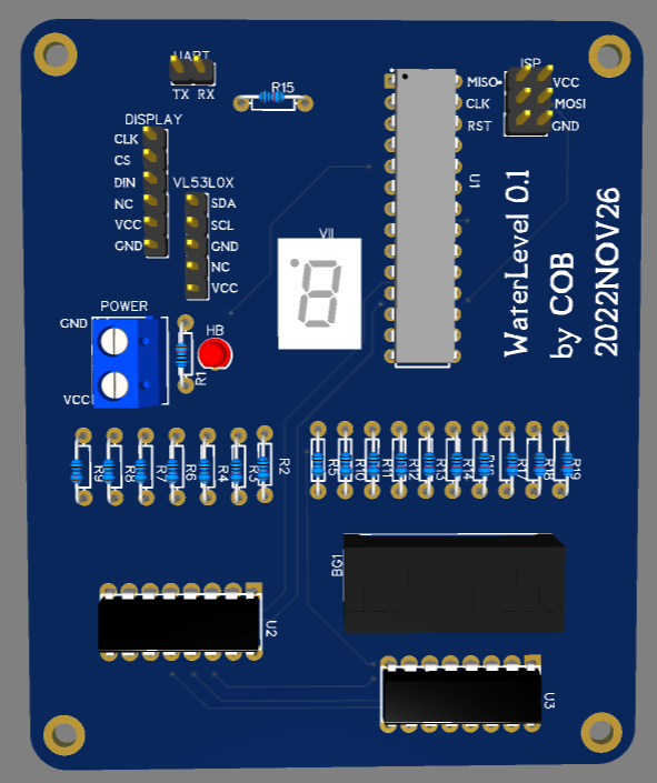
└───Schematics // contains schematics of the project (PDF, easyeda json, pictures of top and bottom view)
|   │   ...
|
└───vl53l0x-non-arduino // library to manage the VL53L0X sensor
    │   ...
Atmega328
The measuring of the water level is done by a VL53L0X sensor, connected throug I2C pins, sitting at the top of the water tank (under the lid), knowing the distance between the sensor and the water surface of a full tank and the height of that surface, the percentage of the current level can be calculated
On the PCB there is an LED connected to PD3, shining at different duty cycles telling that the system is on and runnig
The percentage and some errors code are displayed on a 4 screens MAX7219 display, at startup the full height is flashed
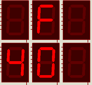
The level in percent and error codes are displayed sequencially on seven segment secreen, one character after another followed by a while character and preceded by a letter telling the message type, for example 53% is represented as "P" "0" "5" "3" " ", an error code of 12 is displayed as "F" "1" "2" " ". The 7 bits of the seven segments are stored in a shift register.
Displaying F12, F24, P089 (89%)
The percentage is also displayed on 10 bits where each bit reperesents 10% of rounded up of the full water, i.e 32 is represented as 4 lower bits set to 1. This could be displayed on LEDs or a bargraph. The 10 bits are split between 2 shift registers and a GPIO : the 1st bit is located at the 8th bit of the shift register of the seven segments (read above), the following 8 bits on the second shift register, the 10th bit is on pin PD4
Displaying progressive values
[   Atmega328   ][  seconds shift register  ][   first shift register    ]
            PD4 ][ Q0 Q1 Q2 Q3 Q4 Q5 Q6 Q7  ][ Q7   Q6 Q5 Q4 Q3 Q2 Q1 Q0 ]
              |    |  |  |  |  |  |  |  |      |    |  |  |  |  |  |  |
           [ A9   A8 A7 A6 A5 A4 A3 A2 A1     A0 ][ G  F  E  D  C  B  A  ]
           [              bargraph               ][    seven segments    ]
Wiring of the bargraph and the seven segments.
The VL53L0X library uses millis (same as arduino) which uses TIMER0 interrupts to count.
The heart beat PWM is gnerated on PD3 which is associated to TIMER2.
The TIMER1 is used to generate an interruption every 10ms, which is used to updated the duty cycle (PWM value) of the heart beat and to execute the shift registers update (bargraph and seven segments display). Which leaves the main thread to handle the initializations, reading values from the sensor, calculating the percentage of water and then display it on the MAX7219.
Thanks to yetifrisstlama for vl53l0x library


