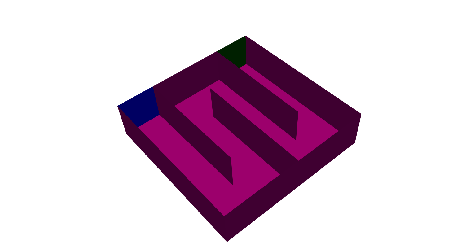
The domain under consideration is a baffled contact tank, as shown in the image below:
The blue surface is the inlet of the domain (patch inlet) and the green surface is the outlet (patch outlet). All of the magenta surfaces are walls (patches walls, bottom, baffle_0, baffle_1, baffle_2). There is also a wall at the top of the domain, which is not shown (patch top).
The mesh is created using blockMesh. Baffles are created by finding common faces between adjacent blocks using topoSet and creating the baffles using createBaffles.
| Boundary Name | Velocity BC | Pressure BC | k BC | epsilon BC |
|---|---|---|---|---|
inlet |
flowRateInletVelocity |
fixedFluxPressure |
turbulentIntensityKineticEnergyInlet |
turbulentMixingLengthDissipationRateInlet |
oulet |
zeroGradient |
fixedValue |
zeroGradient |
zeroGradient |
top |
slip |
fixedFluxPressure |
kLowReWallFunction |
epsilonWallFunction |
bottom |
noSlip |
fixedFluxPressure |
kLowReWallFunction |
epsilonWallFunction |
walls |
noSlip |
fixedFluxPressure |
kLowReWallFunction |
epsilonWallFunction |
baffle.\* |
noSlip |
fixedFluxPressure |
kLowReWallFunction |
epsilonWallFunction |
This case is solved using the steady state solver simpleFoam using the realizableKE turbulence model. Runtime function objects are used to monitor flow rates on the inlet and outlet patches, the residuals of the p and U equations, and the pressure difference from inlet to outlet.
