

Nema 11 Stepper Motor:
This library was tested
with a typical bipolar NEMA-11 stepper motor with four wires:
should work with any similar type motor.
It has 200 steps per revolution, and can operate at at 60 RPM. It was a step to angle ratio of 1.8 degrees per step.
You will need to determine the A, B, C and D wires. With our example motor these are green, blue, black and red.
coil 2.
- Motor black wire A == B+ (A3967)
- Motor green wire C == B-
coil 1.
- Motor red wire B == A+
- Motor blue wire D == A-
A3967:
Info links:
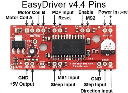
The "Easy Driver" is a motor driver based on the Allego A3967 designed by Schmalz Haus. It is used to drive stepper motors. Each EasyDriver can drive up to about 750mA per phase of a bi-polar stepper motor. It defaults to 8 step microstepping mode. (So if your motor is 200 full steps per revolution, you would get 1600 steps/rev using EasyDriver.)
For the code in this library to work we need to make following connections.
GND : There are three GND (Ground) pins on the Easy Driver. They are all connected together inside the board. Connect the negative side of your power supply, as well as from any other boards you are using to drive the Easy Driver to one or more of the GND pins.
M+ : This is the power input to the Easy Driver. Connect this to the positive power supply lead. This should be a 6V to 30V, 2A (or more) power supply that is clean (low ripple).
A and B : (four pins) These are the motor connections. A and B are the two coils of the motor, and can swap the two wires for a given coil (it will just reverse the direction of the motor). Make CERTAIN that this connection to the motor is solid, and NOT through a connector that has any chance of intermittent contact (which will fry the motor driver chip).
STEP : Connect to RPI GPIO. This needs to be a digital signal. Each rising edge of this signal will cause one step (or microstep) to be taken.
DIR (Direction) : This needs to be a digital signal. Connect to RPI GPIO. The level if this signal (high/low) is sampled on each rising edge of STEP to determine which direction to take the step (or microstep).
MS1/MS2 : These digital inputs control the microstepping mode. Connect to RPI GPIO Possible settings are (MS1/MS2) : full step (0,0), half step (1,0), 1/4 step (0,1), and 1/8 step (1,1).You can also pass in (-1, -1) to software here if you do not wish to use GPIO and wish to hard wire MS-X to logic levels. Do this if your project only uses one type of resolution and you wish to save GPIO pins.
Enable, Reset, PFD and Sleep pins can be left unconnected. They are not supported in this library at present. The User can control them externally with GPIO.
RST (reset) : This normally high input signal will disable all output drivers when pulled low. SLP (sleep) : This normally high input signal will minimize power consumption the output drivers when pulled low. ENABLE : This normally low input signal will disable all outputs when pulled high. PFD : This one is complicated - please see the datasheet for more information.
Also do NOT disconnect motor when in operation, as it will damage controller.
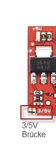
In addition there are two bridges/jumpers on the Easy driver SJ1 and SJ2. SJ1 is jumper APWR and can be left alone, see datasheet for details. SJ2 decides wheter the input Logic is 5v or 3.3V. The RPI needs 3.3v NP The SJ2 is open and set to 5v by default. The user must bridge this jumper to work with RPI, note diagram for location of SJ2 in bottom left.
There are 4 step modes for A3967.
| MicroStep | Step increment degrees | Steps for 1 revolution(360) |
|---|---|---|
| Full | 1.8 | 200 |
| Half | 0.9 | 400 |
| 1/4 | 0.45 | 800 |
| 1/8 | 0.225 | 1600 |
Microstep Resolution Truth Table.
| MS1 | MS2 | Resolution |
|---|---|---|
| L | L | Full step |
| H | L | Half step |
| L | H | Quarter step |
| H | H | Eighth step |
The library file RpiMotorLib.py contains the class which controls the motor. The class is called A3967EasyNema. The test file is called A3967_Nema_Test.py.
init method 3 inputs.
| ID | Name | Type | Help |
|---|---|---|---|
| (1) | direction | int | GPIO pin connected to DIR pin of IC |
| (2) | step_pin | int | GPIO pin connected to STEP of IC |
| (3) | mode_pins | tuple of 2 ints | GPIO pins connected to Microstep Resolution pins MS1-MS2 of IC, You can also pass in (-1, -1) here if you do not wish to use GPIO to set MS. |
motor_move method 6 inputs.
| ID | Name | Type | Default | Help |
|---|---|---|---|---|
| (1) | stepdelay | float | .05 | Time to wait in seconds between steps |
| (2) | steps | int | 200 | Number of steps sequence's to execute. |
| (3) | clockwise | bool | false | Turn stepper counterclockwise |
| (4) | verbose | bool | false | Write pin actions to console |
| (5) | steptype | string | Full | type of drive to step motor 4 options(Full, Half, 1/4, 1/8) |
| (6) | initdelay | float | 1mS | Initial delay after GPIO pins initialized but before motor is moved. |
Another method is called to stop the motor when the motor is moving. motor_stop(), if you wish to stop motor before end of its run. You can also stop with keyboard interrupt.
Example:
import RPi.GPIO as GPIO


# import the library
from RpiMotorLib import RpiMotorLib

#GPIO pins
GPIO_pins = (6, 13) # Microstep Resolution MS1-MS2 -> GPIO Pin
direction= 26       # Direction -> GPIO Pin
step = 19    # Step -> GPIO Pin

# Declare an named instance of class, pass GPIO-PINs
mymotortest = RpiMotorLib.A3967EasyNema(direction, step, GPIO_pins)

# call the function, pass the arguments, In this example
# we move 200 steps in full mode(one revolution) after an initdelay
# of 50mS with step delay of 5mS, Clockwise direction and verbose output on.

mymotortest.motor_move(.005, 200 , False, True, "Full", .05)