USB keyboard/mouse to PS/2 interface converter using a Raspberry Pi Pico
 |
 |
 |
 |
|---|
Keyboard only (incl. PC-XT) variant: https://github.com/No0ne/ps2pico
There is also an alternative ps2pico firmware for the PC-XT and ps2x2pico hardware: ps2pico-XT-alt.uf2
PicoMiteVGA variant: https://github.com/No0ne/hid2cdc
PiKVM integration:
ITX-Llama integration: https://github.com/eivindbohler/itxllama
- Download
ps2x2pico.uf2from https://github.com/No0ne/ps2x2pico/releases - Copy
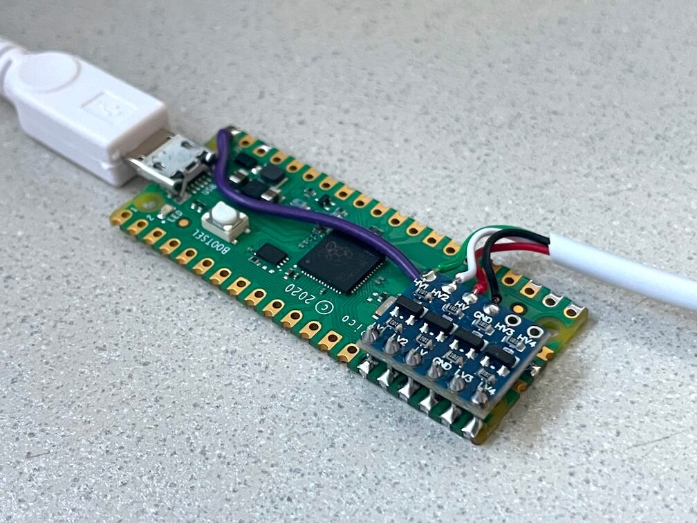
ps2x2pico.uf2to your Pi Pico by pressing BOOTSEL before pluggging in. - 3.3V/5V conversion is done using a bi-directional level shifter: https://learn.sparkfun.com/tutorials/bi-directional-logic-level-converter-hookup-guide/
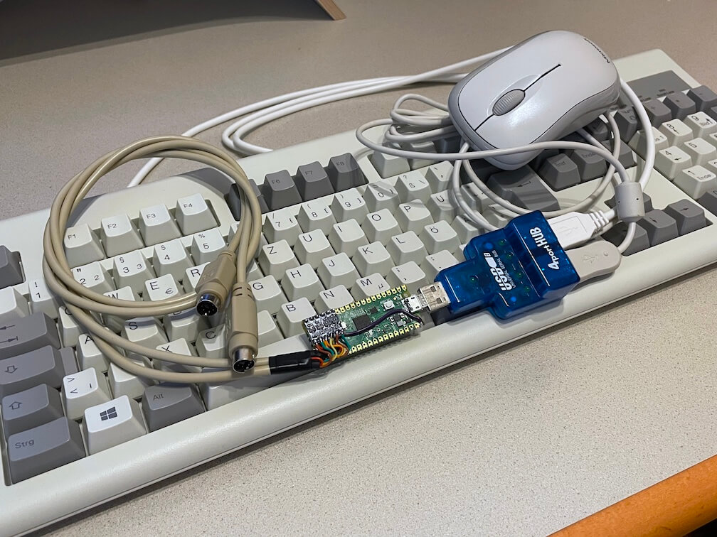
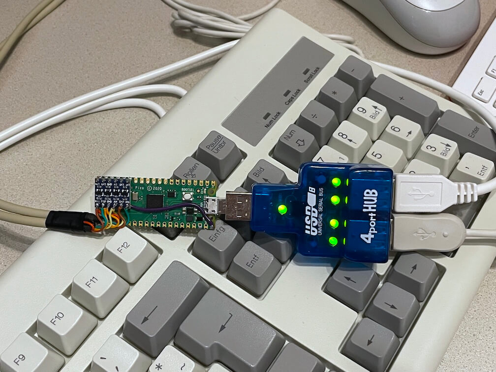
- Afterwards connect a USB keyboard and/or mouse using an OTG-adapter and optional USB hub.
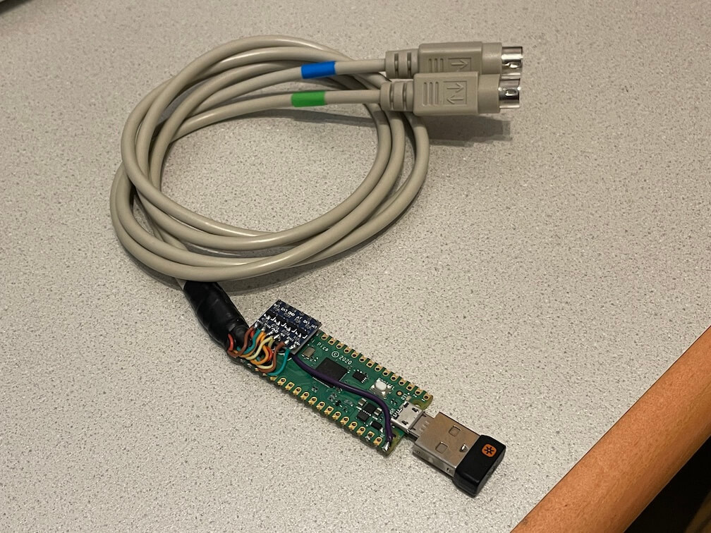
- Also works with wireless keyboards and mice with a dedicated USB receiver.
Check the power consumption of your keyboard/mouse/hub first before plugging in!
If you also want to use a real PS/2 keyboard and mouse together with your USB devices you can mount another level shifter on top of the pico. These two ports work as PS/2 inputs and are passed through to the PS/2 output ports.
- GPIO3 LV1 - keyboard data
- GPIO4 LV2 - keyboard clock
- GPIO5 LV - 3.3V pull-up
- GND - GND
- GPIO6 LV3 - mouse data
- GPIO7 LV4 - mouse clock
Don't forget to wire HV to 5V and your PS/2 sockets to power the connected PS/2 devices.
PS/2 passthru is especially useful with the PiKVM Pico HID or Pico HID Bridge as you can continue using your existing peripherals.
- GPIO26 LV1 - keyboard data
- GPIO27 LV2 - keyboard clock
- GPIO16 LV3 - mouse data
- GPIO17 LV4 - mouse clock
Don't forget to wire LV to 3.3V and GND to GND separately as the level shifter does not fit directly on top of the pico.
You can hook up a USB serial adapter to GPIO0 for additional debugging output. The serial settings are 115200 baud, 8 data bits and no parity. You can also use another Pico running the pico-uart-bridge for this.
Install needed libraries and tools:
sudo apt install cmake gcc-arm-none-eabi build-essential pkg-config libusb-1.0-0-dev libusb-1.0-0Get the Raspberry Pi Pico SDK version 1.5.1:
git clone https://github.com/raspberrypi/pico-sdk
export PICO_SDK_PATH=/path/to/pico-sdk
cd $PICO_SDK_PATH
git checkout 1.5.1
git submodule update --init
Update to the latest TinyUSB release 0.17.0:
cd $PICO_SDK_PATH/lib/tinyusb
git checkout 0.17.0
Generate the UF2 file:
cd /path/to/ps2x2pico
mkdir build
cd build
cmake ..
make- https://github.com/No0ne/ps2pico
- https://wiki.osdev.org/PS/2_Keyboard
- https://wiki.osdev.org/PS/2_Mouse
- https://wiki.osdev.org/Mouse_Input
- https://wiki.osdev.org/%228042%22_PS/2_Controller
- http://www-ug.eecg.toronto.edu/msl/nios_devices/datasheets/PS2%20Keyboard%20Protocol.htm
- http://www-ug.eecg.utoronto.ca/desl/nios_devices_SoC/datasheets/PS2%20Mouse%20Protocol.htm
- Archive.org links for the dead links in the pages above