-
Notifications
You must be signed in to change notification settings - Fork 48
Tutorial
This tutorial will guide users through downloading and installing the pre-built Windows Pothos SDR development environment. Users will make sure that their SDR devices are installed properly and can communicate with the environment. And finally, the tutorial will cover building a simple visualization application in the Pothos GUI. Lets get started!
Table of contents

- Grab the most recent copy of the PothosSDR.exe installer from the Downloads page
- Run the installer and make sure to choose "Add PothosSDR to the system PATH"
- For the sake of simplicity, the tutorial uses an install path of C:\PothosSDR

Once the development environment is installed, you should ensure that your SDR device is visible to the system. Typically this step involves installing system drivers (PCIe/USB) or configuring network interfaces, depending upon your device's PC interface. Since its not possible to document the instructions for every device and every driver here, we recommend following the instructions from the manufacturer's website or the device driver's home page.
USB-based SDR devices typically use libusb. The first thing to do for a USB device is to make it available under libusb using Zadig. Simply attach your SDR device via USB and run Zadig on every unrecognized device. A copy of Zadig is included in the root of the development environment.

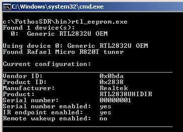
Standard command line utilities for your device will be available in C:\PothosSDR\bin In the example below, we use rtl_eeprom.exe to demonstrate that the RTL device can be detected and communicated with through its device driver.
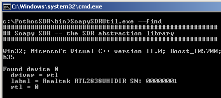
Next, we will confirm that Soapy SDR can find your device on the system. If Soapy SDR can locate the device, then it will be usable within Pothos through the SDR source and sink blocks. After installing the device's system drivers or configuring the network interface appropriately (as per the manufacturer instructions), use the SoapySDRUtil.exe command line utility to locate the device:
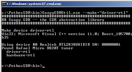
Once the device can be found on the system through the SoapySDRUtil.exe, it can be instantiated using the same discovered key/value identifiers:
Lets get started by visualizing sample data from the SDR device!
At the root of the SDR development environment, there is a launcher shortcut for Pothos GUI. To launch Pothos GUI, open C:\PothosSDR in the windows explorer and double click on the PothosGui.exe launcher:
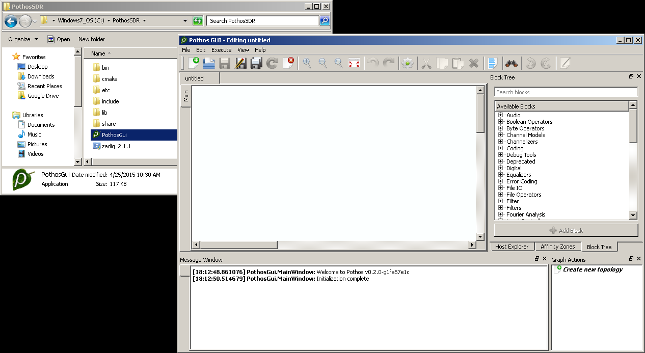
- Users may get a warning about firewall rules when launching the Pothos GUI. The GUI launches various sub-processes and communicates with them over TCP. Make sure to allow the firewall exception for Pothos GUI for proper operation.
- Pothos may print an initialization error about loading the Python support module. This is a harmless error that happens when the Python environment is not installed. To create and use Python-based processing IP, read more in the development section.
To visualize spectrum, we will the SDR source block for collecting samples, and the Spectrogram plotter for visualizing the sample stream. Locate these blocks in the block tree using the search feature, drag and drop them into the editor, and connect the source to the plotter.

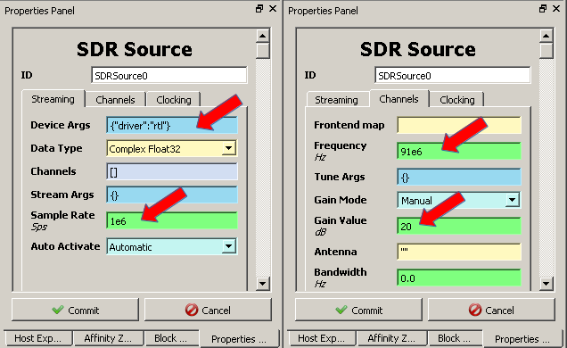
Before continuing, the SDR source block must be configured. Double click on the source block, and enter the desired device arguments, sample rate, gain, and tune frequency. Device arguments are key/value pairs used to identify a specific device. If this is the only SDR device on the system, then empty brackets "{}" will suffice.
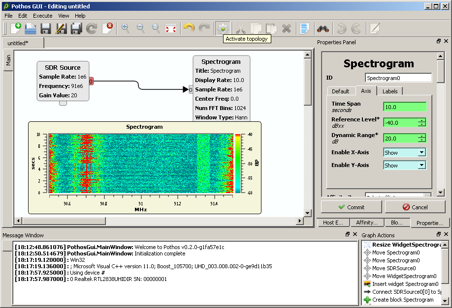
After instantiating, configuring, and connecting both blocks, right click on the editor and select "Insert graph widgets" to insert the plotter. Then click "Activate topology" in the toolbar or menu to visualize the spectrum.

- Checkout the Pothos GUI tutorial to learn about instantiating and connecting blocks, inserting graphical widgets, and much more.
- Interested in creating custom processing blocks or driver development? Checkout the Developing IP wiki page.
