I started a rudimentary, software-only piano tuner experiment.
Abandoned the software experiment.
I hack together some notes for a possible hardware implementation of a piano tuner, thinking about:
- Needles for octave, note in octave, tuning in note, volume
- Lamp for power
- Lamps behind needle dials
- Capacitive fade-in for lamps
- Glass or plastic bead in front of power lamp
- Phonograph-style mic pickup
- Clock hands for needles
Initially I assume it'll run a Fast Fourier Transform, and toy with the idea of using a Texas Instruments LEA (Low-Energy Accelerator). That would be good if we're making 10,000 of these things, but it would be a steep learning curve.
All of this goes into a Google Doc and then somewhat forgotten about.
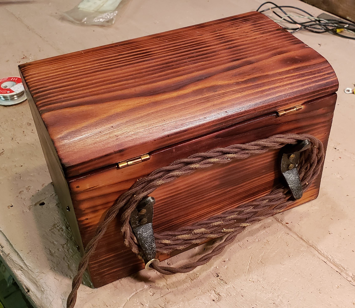
I found an antique-style wooden box on Facebook Marketplace. It's pretty clearly one-of-a-kind, and was hand-made in an Egyptian workshop by a late relative of the seller. It's perfect.
In around now, plotting starts to solidify for a hardware tuner.
Wife orders copper foil for the horn. I order the USB microphone that will be connected to the Raspberry Pi 4 I have on hand.
Orders for more power accessories: 5V 25W power supply, and a nice little USB-C-to-terminal-block power adapter to power the Pi without having to jankily connect a cell phone charger on the inside of the enclosure.
Ordered a handful of gauges, 5Vdc analogue, of various sizes:
These are coming from China so I'm expecting it to take forever for them to get here, but anything in North America is exhorbitant. The intent is to replace the faceplate with a custom one and backlight it if possible.
Order some vintage-style electrical accessories from Vintage Wire & Supply. They're relatively expensive but look incredible.
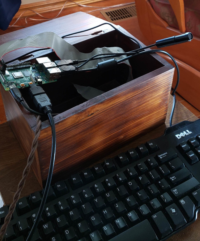
Pictured above: temporary keyboard on the bottom; open box (so far unmodified) in the middle with the Raspberry Pi board sitting on top of it; USB microphone sticking out to the right. The ribbon cable is for a real-time clock that is also temporary. On the left you can see the twisted brown cotton vintage-style 120VAC cord.
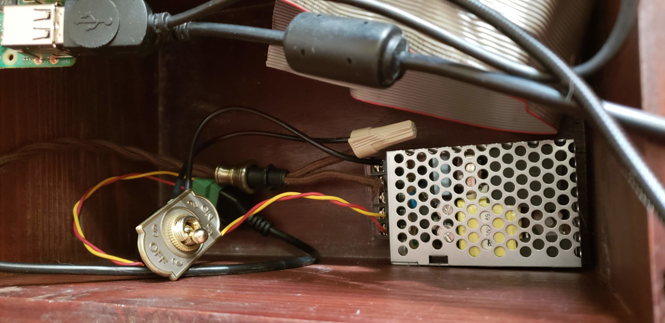
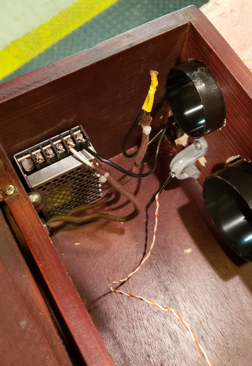
Pictured above: power components sitting in a temporary arrangement in the box. Far centre left is the brown 120VAC cord, running to a brass stress relief in the middle that will eventually be in the side of the box. Centre is a white marette to the switch. Lower left is the antique switch that will be mounted to the exterior of the box. Lower right is the MeanWell power supply; more rugged and well-ventilated than the typical cell phone charger. The red-yellow cord runs 5V from the power supply to a small green terminal block, in turn through a USB-C cable to the Raspberry Pi on the upper left.
Going on vacation. The wife has let me bring a pile of tech goodies to work on this project.
Using the same GitHub web page, resuscitate the tuner project, but with hardware in mind. The Raspberry Pi, keyboard, mouse, microphone and cell phone power supply are set up on the coffee table of the cottage, and I have a great time getting going on development.
Start using the Simple Direct Layer for microphone capture on the Raspberry Pi. Pretty much immediately throw that out the window in favour of the underlying Advanced Linux Sound Architecture.
Research into the best way to detect pitch. Intend on running autocorrelation for note detection, in line with the findings of Coert Vonk, and associated research by Brown and Monti.
Some of it makes no sense to me so I post on a Digital Signal Processing forum.
Ordered some Microchip PIC16LF1773 (programmable interrupt controller) from Mouser, since DigiKey was nearly out of stock. These devices have a mix of 5- and 10-bit unbuffered DACs that can be internally buffered with three op-amps; they also support UART, I2C and SPI - so one way or the other they'll definitely be able to talk with the Pi.
Start using the Gnu Scientific Library with the intent of applying it to the autocorrelation work.
Throw GSL out the window in favour of ATLAS (Automatically Tuned Linear Algebra Software), an implementation of BLAS (Basic Linear Algebra Subprograms).
The gauges arrived from China, quicker than I expected! They're wonderful little devices, fully disassemble-able with two screws on the side, and come pre-packaged with hardware for the mounting bolts. There's a high-accuracy resistor in each, and the input impedance is a little over 5k, so the PIC can definitely handle it.
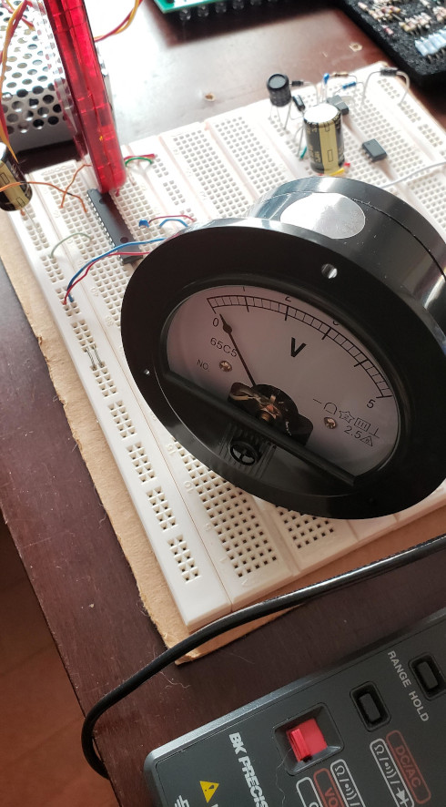
Upper left: chassis of the power supply; with the red PICkit 3 programmer in front of it, plugged into the breadboard.
The breadboard has the intended DAC PIC just below the PICkit.
On the gauge itself: the sticker on the top will be discarded; the front plastic pane and surrounding cylindrical cover come off with two screws on the side (not shown); then the instrument plate comes off with two bolts on the front.
Start a PIC firmware project to act as a DAC (digital-to-analogue converter) for the Raspberry Pi.
Start an Eagle schematic to plan out how the DAC will be connected.
Parts I still need to dig up or buy:
- Amber LEDs for the gauge backlights
- Perfboard
- Rectangular cable to run from the Pi to header on the perfboard
- A rail-to-rail 0-5V buffer op-amp for the one remaining unbuffered DAC output
I also need to upgrade the Pi to a 64-bit operating system, since I didn't realize I had been using a deprecated 32-bit Raspbian.
Also need to write a calibration routine that gives me interquartile range for the harmonics at various notes.
Consider using a nice amber LED for backlights; such as the Lite-On LTL-1CHA with
- 3mm diffusion lens
- 20mA max, 2.1 volts forward
- 60° half-power angle
- Wavelengths: 602 nanometres dominant, 610 nanometres peak
If we use 10mA, we need 270R limiting each LED. For fade-in with a capacitor parallel to the LED, and a time constant over 2 seconds, we need a large capacitor of ~10mF.
The capacitive fade-in option kind of sucks. The capacitors needed are big and expensive, and all four could be replaced with a single 40mA MOSFET driven by PWM from the PIC. Another advantage of PWM would be that it works right away, where as capacitive charge has to go through a dead zone where the forward voltage is below that needed by the LED.
The PIC16F1773 supports 10/16-bit hardware PWM with a bunch of different sources. PWMs 3, 4, 5, 6, 9 and 11 all support PPS and at least one of them can output to each of PORTA/B/C, respectively. Compare/capture/PWM (CCP) modules 1, 2, and 7 likewise can output to at least one of those ports.
The hardware solution would have charged by
V(t) α 1 - exp(-t/𝜏)
with 90% by
t = -𝜏 ln(1 - 0.9)
If we want 90% in two seconds, 𝜏 ~ 0.8686, and our time expression becomes
V(t) α 1 - 0.1^(t/2)
A piecewise linear approximation would depend on the derivative:
dV/dt = 1/𝜏 exp(-t/𝜏)
      = -ln0.1 / 2 * 0.1^(t/2)
If we increment 8 of the 16 bits in the duty cycle for a PWM, the configuration would be
EN = 1
MODE = 00 (standard)
PRIE = 1 (interrupt on period match to update duty)
PS set to divide between 2^0 and 2^7
CS either HFINTOSC (16MHz) or LFINTOSC (31kHz) - both sleep-compatible
OFM = 00 (independent run)
We will be starting DC at 0, DC delta at a high value, and applying a simple binary exponential decay algorithm on the delta. To find the initial delta value we need to work backward: at the end of the curve, the delta will only be 1, representing 2^-8 of full deflection. The last intersection of the exact and approximate curves is at
-𝜏 ln(2^-8) ~ 4.817 s
At this time, the derivative is
1/𝜏 * 2^-8 ~ 0.004497
The time it takes to increase 2^-8 is, with an initial tangent,
2^-8 𝜏 exp(t/𝜏)
which starts as 3.4 ms. If we only did this for one cycle, we could still have a PWM rate of 295 Hz. Assuming a PR of 0x100,
Period = (PWMxPR + 1) * prescale / clock
prescale = log(16e6 * 2^-8 𝜏 / (2^8 + 1)) / log(2) ~ 7.72 > 7
The slowest prescale for 16-bit PWM is 2^7, which would mean a period value of
2^-8 𝜏 * 16e6 / 2^7 - 1 ~ 423 > 2^8
which would require carry operations during PWM update. If we go the other way, disable the prescaler and use LFINTOSC=31kHz,
2^-8 𝜏 * 31e3 - 1 = 104
TMR2IE probably won't work in 10-bit mode, because the timer is cleared on
period match.
It's also worth noting that the transfer function for duty cycle to lumens is assumed to be linear but probably isn't.
Some of the above will stay true and some won't. The problem with having a fixed delta update rate is that eventually, the delta would need to be fractional, and we're only using integer math.
This is a very powerful device; we could pursue any of the following as alternatives:
- Use 16-bit PWM, interrupt on
PRIF, increment a soft post-scaler, incrementPWMxDCon post-scale overflow, double post-scale factor every 140PRIFs - Use 10/16-bit PWM, short
PWMxoutput toTMR4_clkinput, incrementPWMxDCHon everyTMR4IF, shortPWMxoutput toTMR6_clkinput, doublePR4on everyTMR6IF - Use CLC with two internal PWM/CCP inputs, offset by a beat frequency
- Use COG with two internal PCM/CCP inputs, offset by a beat frequency
For the last one, we'd have:
COG1CON0EN= 1CS= 0b10 (HFINTOSC, sleep-compatible)MD= 0b000 (steered PWM)
G1RIS9= 1 (PWM5 for rising)G1FIS10= 1 (PWM6 for falling)COG1STRA= 1 (output on steering channel A)
Continuing the silliness above, I've posted a detailed solution.
A month, more math and experimentation later, the LED fader is done. As it turns out, the luminosity transfer function seems to be visually exponential so I can get away with a linear ramp.
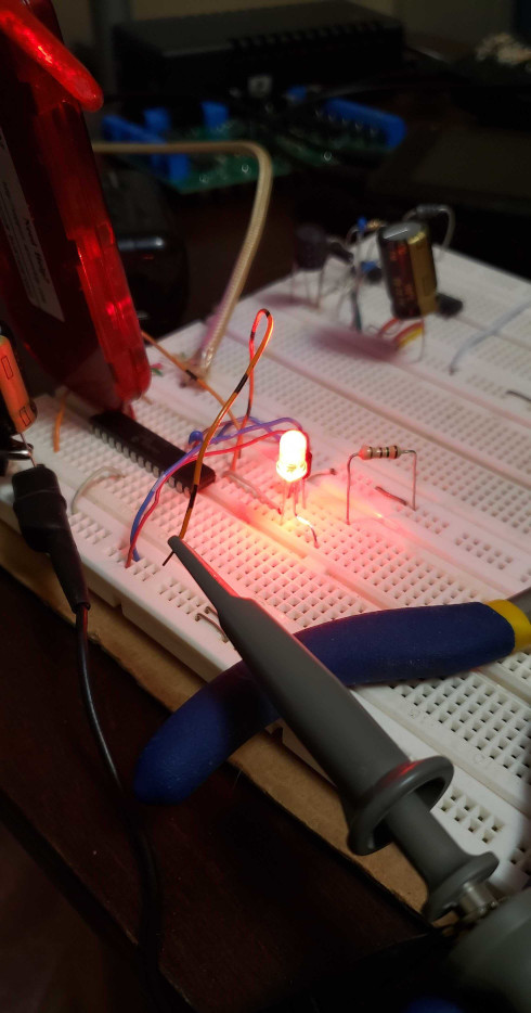
The very bright red LED used in this test will not be used in the final system but is working fine nevertheless. This one is so bright that it illuminates my ceiling at 20mA.
New parts ordered:
- the protoboard where stuff will get soldered (though-hole only),
- the nice amber LEDs,
- some rectangular cables for SPI, and
- some rail-to-rail operational amplifiers - only one is needed as a buffer for a digital-to-analog converter output; the other outputs have buffers already.
Did a rough layout of the digital-to-analog converter circuit as it will be on the protoboard.
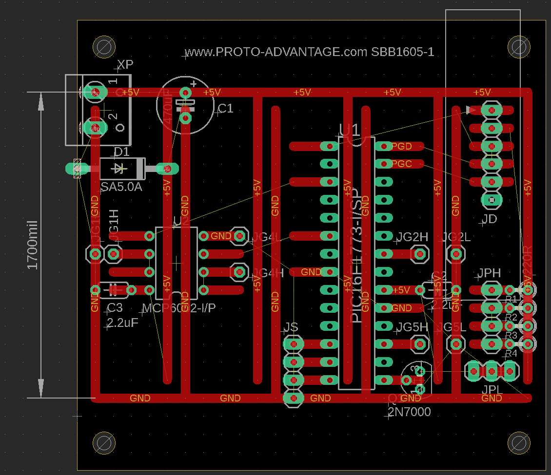
- Upper left: the power entry block
- Mid-left: the buffer chip "U2" for gauges. Only one of the two channels is strictly necessary, but use both to offload a tiny bit more current from the MCU and prevent floating.
- Centre: the MCU (microcontroller) "U1" that the Raspberry Pi will talk to, with its SPI (serial port) "JS" on the bottom.
- Lower-right: gauge backlight PWM driving circuit, four-channel
- Upper-right: programming/debug connector "JD".
The red traces are copper on the board's top layer. The thin yellow lines are ratsnest that I need to wire and solder myself.
This efind script shows that it's possible to null a fixed, positive offset
voltage on the MCP6002 operational amplifier I use for DAC buffering.
    Vdd = 5
    Voff = 4.5e-3
    R2 = 0

    def find_r4(R6: float, R5: float, R1: float) -> float:
        return (R5/R6 + 1) * R1 * Voff/Vdd

    def find_r3(R6: float, R5: float, R1: float, R4: float):
        R4R3 = R5/R6 - R4/R1
        if R4R3 == 0:
            return float('inf')
        return R4 / R4R3

    def find_vo(Vi: float, R6: float, R5: float, R1: float, R4: float, R3: float) -> float:
        Vin = Vi*R6/(R6 + R5) + Voff
        I3 = Vin/(R2 + R3)
        I1 = (Vdd - Vin)/R1
        I4 = I3 - I1
        Vo = Vin + R4*I4
        return Vo

    s = Solver(
        (
            Resistor('6', E24, None, 1e6, 10e6),
            Resistor('5', E96, None, 1e3, 10e3),
            Resistor('1', E96, None, 1e6, 10e6),
            Resistor('4', E96, find_r4),
            Resistor('3', E96, find_r3),
        ),
        (
            Output(
                'Vol', 'V', 0,
                partial(find_vo, 0),
            ),
            Output(
                'Voh', 'V', Vdd,
                partial(find_vo, 5),
            ),
        ),
        1e-5,
    )
    s.solve()
    s.print()
It outputs:
    R6      R5      R1      R4      R3        Vol      Err        Voh      Err
1.5 MΩ 4.42 kΩ 1.13 MΩ 1.02 kΩ  499 kΩ  -13.99 nV -1.4e-08    5.000 V  3.7e-07
1.6 MΩ 6.49 kΩ 1.87 MΩ 1.69 kΩ  536 kΩ  -461.3 nV -4.6e-07    5.000 V  1.9e-06
1.0 MΩ 10.0 kΩ 1.00 MΩ   909 Ω  100 kΩ  -4.500 nV -4.5e-09    5.000 V -5.0e-06
1.0 MΩ 10.0 kΩ 10.0 MΩ 9.09 kΩ 1.00 MΩ  -4.500 nV -4.5e-09    5.000 V -5.0e-06
But I won't actually do this nulling, for reasons listed here.
When my brothers play Path of Exile with me, they have taken to calling its crafting workbench "[my] actual workbench" due to its electrified animations. Currently, on the first day of my latest vacation, my mobile workbench looks like this:
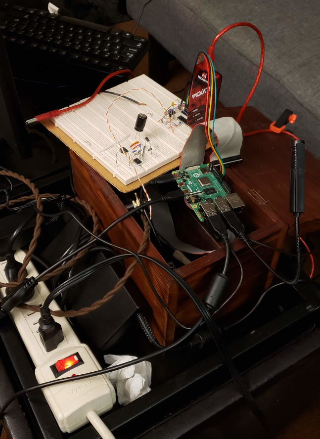
This marks the first time that the breadboard is connected to the Pi via a 4-conductor wire carrying SPI. The SPI microcontroller firmware was written last weekend but hasn't been tested yet. The buffer op-amp is connected and initial gauge tests work. The gauge input posts are left-negative, right- positive when looking from the front.
I've also (finally) started using a 64-bit OS for the Raspberry Pi 4.
Next is to:
- based on the
documentation,
put the SPI module in 8-bit,
SPI_NO_CSmode - work off of the Raspberry Pi/Linux SPI test code
If I end up adding a back-illuminated bead for power indication (which now seems a little redundant to me given that the gauges are already illuminated on power), one option if I can't find anything better is this thing from Michael's:
- Item 10402037
- 18mm diameter faceted glass
- It's labelled "crystal", though I don't know how far to trust that
A very attractive option from the Bead Boutique is their quartz "nuggets":
- Natural clear quartz
- 22x15mm "medium focal" size
As for gauge illumination, the LTL-1CHA is way (way, way) too dim to be useful for backlighting. On the next DigiKey order I'll be switching to high- brightness amber LEDs from Cree. Looking at the gauge interior again, it does look like a LED mounted at the inner rear of the gauge would need an eyeballed 30 degrees to either side, or 60 degrees total, without some other diffusion scheme.
The woodworking portion began. I sought some external expertise from my parents about the best way to cut circular holes for the gauges. I had started with a drill and then (massive) reciprocating saw, not realizing that we have a jigsaw ("autoscroller") better-suited to the job. All of the gauge holes were then done by drill, jigsaw, and then dremel sanding to creep up to a snug fit.
The first (gnarly) cuts:
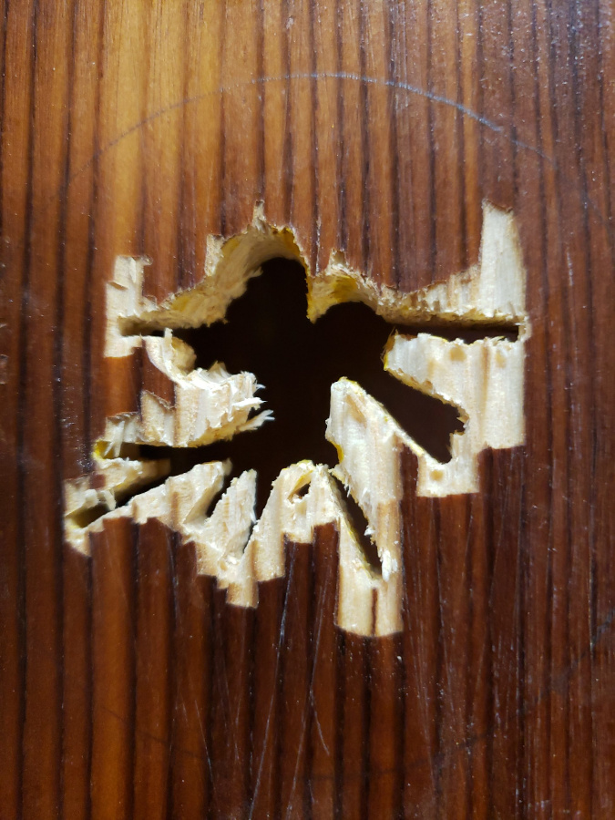
This was time-consuming but straightforward. The rear power intake stress relief was also straightforward. The power indicator was especially lucky: the quartz teardrop, on its end, fits very well into a hole made by a standard drillbit and is so snug that it probably won't require glue.
The biggest problem was the power switch. The threaded shaft was too short compared to the thickness of the wood. A fancy solution would be to recess the front plate, but I'm not good enough to do that and anyway it wouldn't look as good as the alternative: ablate a hole for the switch body on the inside of the box. Given that the box is already assembled and I refuse to disassemble it, this was a huge pain in the ass and required many passes with an awkwardly- angled dremel. I got it down to the point where there was barely enough thread protruding for the front finishing nut to grab, and: good enough.
To do:
- Still need at least one more hole, for the microphone and/or the horn neck
- The wire cleats still need to be attached to the back
- Replacement gauge backlights ordered and installed
- Power indicator dimmed (330R is way too bright) and LED somehow mounted
- Ideally brass screws installed for all gauges
- Maybe re-sand and stain surface? Or leave it looking beat up.
For gauge fastening nuts, they need to be #4-40 (slightly less than 1/8" diameter shaft), slightly less than 1/4" diameter head, and at least 3/4" long if a nut is to be applied on the inside. McMaster-Carr carries brass bolts that would do the job but apparently some family members have equivalents in stock, so I won't place an order. (I also considered Acklands-Grainger but it seems that they aren't shipping anything until the end of January.)
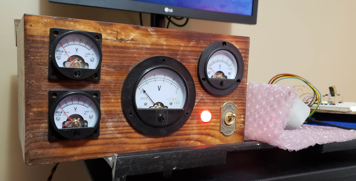
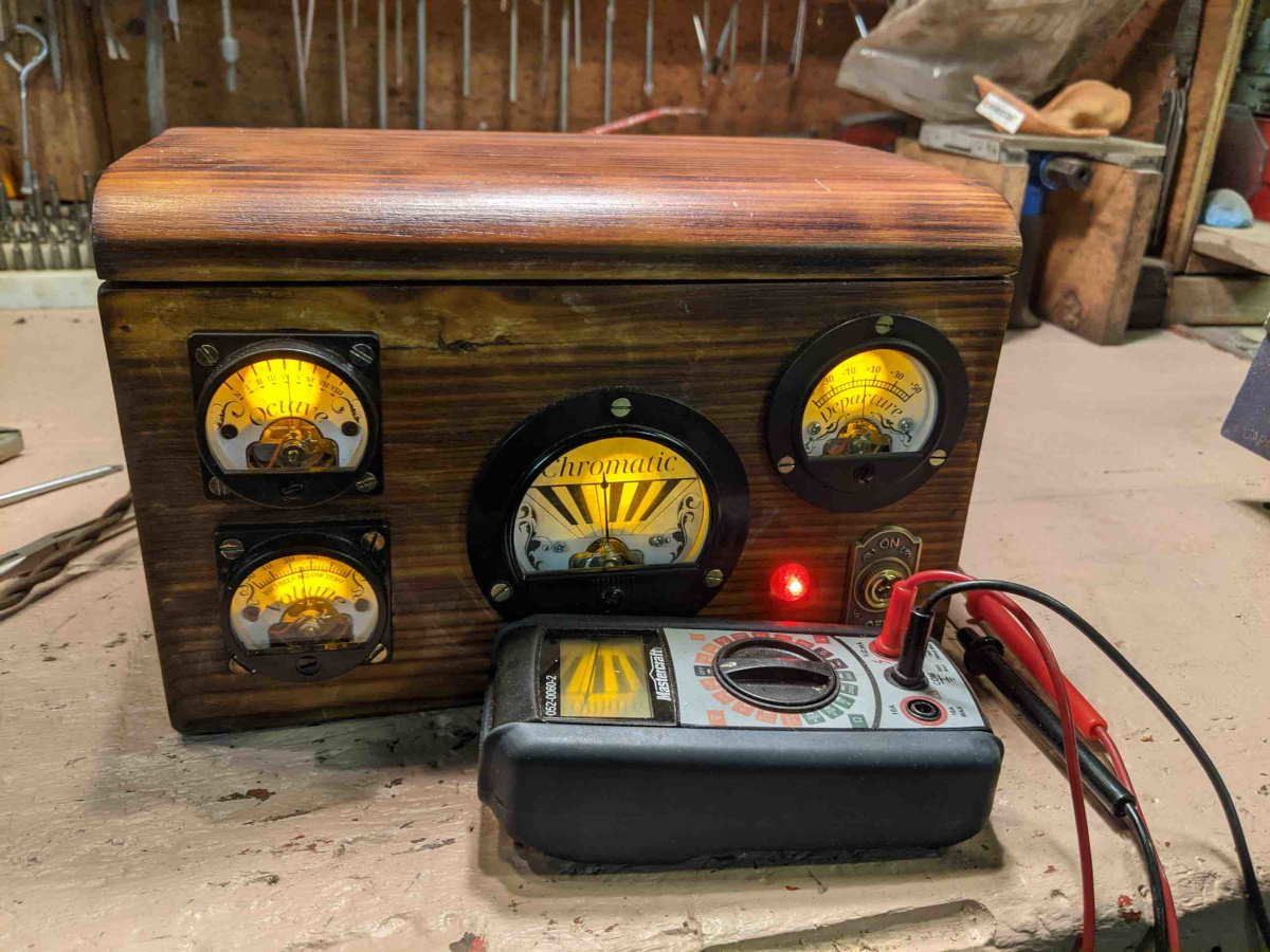
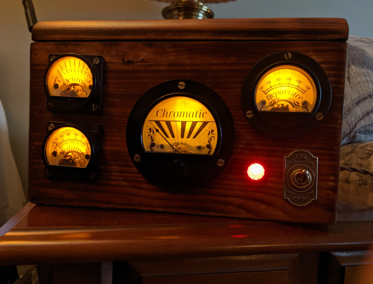
Working moving gauge demo end-to-end. Also, the new backlights are in, and have a very nice hue and what will certainly be enough brightness. I'm worried about how narrow the light cone is, but I'll deal with that with a secondary diffuser if I have to.
Wire cleats, power supply, strain relief and power indicator light all mounted.
The power indicator looks fine with a little over 1mA from a 2.2k resistor. By contrast, the backlights will need to be fairly bright, close to the recommended maximum drive current of 30mA through 38 ohms. That resistor had to be approximated from a parallel 51 and 150 because it's what I have on hand and doesn't merit a new parts order. With this 38 ohms, the current is shared with two LEDs in series, which doubles the drive efficiency and allows us to drop the drive FET - since 60mA is easily within the 100mA tolerated by the PIC's high-drive mode. In addition to high-drive mode, the PIC port can be put in open-drain mode (though I found a bug in the Microchip vendor header where some registers are misnamed or missing, but there's an easy workaround).
Today we started cutting gauge faceplate plastic out of a recycled salad container. Paper will be glued to the front of these.
Soldering almost done, save some LED wires:
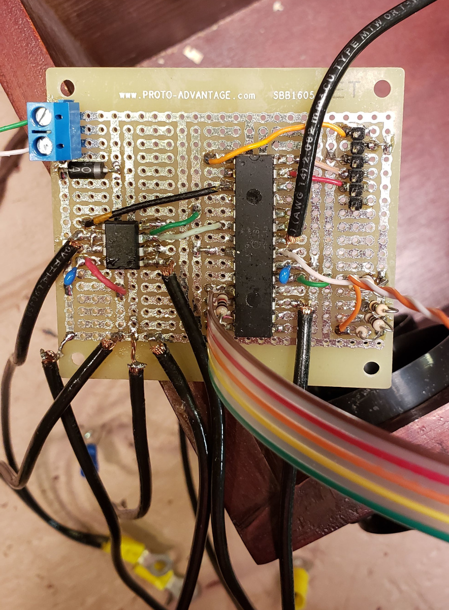
I don't like soldering very much, and I'm not great at it, but the board works (at least for the PIC and the power LED fade, so far).
Most of the gauge art is done in Gimp. I'm working in 600 DPI, and trying to carefully preserve radial accuracy while substituting gauge scale graphics. Only missing is the decibel scale.

More family help has come in the form of math to accurately identify frequencies:
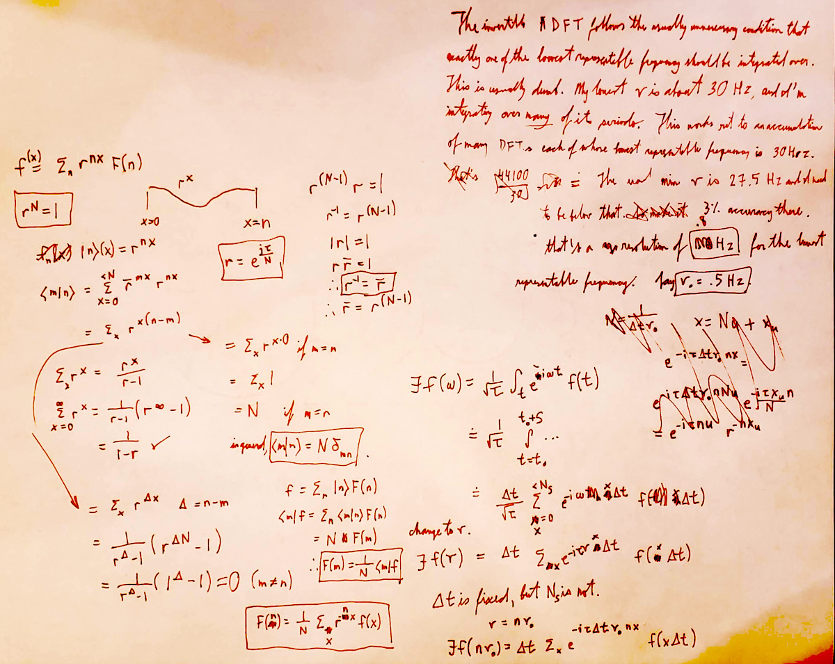
Well, it's been gifted - though it isn't done yet, and I imagine will continue to be a labour of love for some time, particularly in software refinement.
Even more family help arrived in the form of pinning down some pesky circuit issues with a backlight and a gauge. Those seem to have stabilised, so we can finally focus on the software in more detail.
As I feared, the light cone is indeed both too sharp and narrow from the LEDs compared to what I would have preferred, so if I'm feeling extra ambitious or bored and want to de-solder and de-glue the existing LEDs, I would replace them with fancy oval ones that have wider viewing angle; or add some diffusion material.
We're now in the "long tail" of refinements. One of the trickiest bits - fixing up a gauge winding that was tangled, trimming some gauge surfaces that were rubbing, and general finagling was needed to get the gauges to move reliably, and my family was instrumental in getting that done.
Other family help came in the form of a brilliant idea for the diffusion problem - simply rough up the LED lenses. This does exactly what it should:
There's a pesky and difficult-to-reproduce microcontroller hang that we might eventually be able to solve, but in the meantime we're converging on something that actually works.
The microcontroller issue has probably been squashed. Previously we'd been putting the microcontroller directly to sleep after detecting an out-of-sync issue, but that was likely causing some following data to be dropped. The safer thing to do is - if we get out-of-sync, stay awake, and don't sleep until (a) we know we're in sync and (b) a complete packet has been received.
After a long period of dormancy, the project got new attention from my brother who reverted the Pi from Arch Linux to the stock PiOS. The DAC microcontroller is dead. He passed the box, board and all, to me several weeks ago, then - for a week through today - visited me in person. Whereas it started off being tuner-themed, the majority of the time ended up being an (extremely productive) organisation spree. We also visited a local electronics shop to buy connectors and a new, more spacious board, as well as a comparator to be configured for level shifting.
We needed to buy a level shifter, or at least something to build one, because the RPI and PIC operate at very different logic levels. I don't remember why, at the time, I deemed it OK to omit a level shifter, especially given sketchy and very different outputs seemingly exceeding the Pi's own digital rail; but this time around we need to rule out more things to not fry the poor micro again.
The comparator we bought is a KA393. After a first prototyping effort failed, I did some more research and found out that - to my surprise - it's open-collector, which really complicates things.
Something like the following will have to be used -
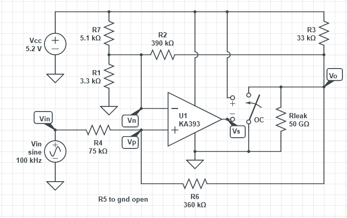
This needs to meet several requirements:
- Compatibility with the observed, and different, clock and MOSI levels in my notes
- Conversion up to 5V for the PIC
- Noise immunity via hysteresis, which for now I'm assuming will run from 1.2 through 2.8 volts
- Ability to support a resistive pullup without throwing the positive and negative feedback gains out of whack
- Pullup not too small, or else it will drag up the comparator's saturation voltage
- Pullup not too large, or else the high voltage won't be high enough for the MCU
- Account for a bias current of 65 nA
- Account for what is now (in the Z-output case) a non-trivial resistive network with no isolation between the negative and positive branches
- Account for discretisation error due to E-series resistors
- Don't blow up the comparator by giving it too high a common-mode input
In this case I've given up on pen-and-paper first-principles calculation, and wrote
level_shifter.py.
In the interior optimisation loop, it uses scipy.optimize.root: a vector-valued root-finding
function which wraps Argonne National Laboratory MINPACK's hybrid implementation of the
Powell method. This is used to solve two
KCL
systems, one for the output-Z hysteresis transition case and one for the worst-case common-mode
input. With five voltages as degrees of freedom and the entire resistive network as given, it
solves the trickier network problems in acceptable time - even when given many dozens of vector
dimensions from the outer loop.
The outer loop needs to be MINLP - mixed-integer nonlinear programming. This stage of the
optimisation needs to be discrete (integral) because of the
E24 series; I'd prefer not to
buy exotic resistances from the internet. It's nonlinear because both several voltages and all of
the resistances are unknown, and they multiply with each other. I only know two free solvers. The
first is scipy.optimize.differential_evolution and the second is
APOPT as wrapped by GEKKO. I use
the former for convenience. It's an implementation of a 1997 Storn-Price stochastic population
method and does support bounded integral variables. It's slow, but that's fine.