You cannot use any CC2531 based device with Tasmota! CC2531 supports USB communication and not serial communication required by Zigbee2Tasmota.
| CC2530 with PCB antenna, DL-20 | CC2530 with external antenna | CC2530 with external antenna and CC2591 RF front end |
|---|---|---|

|

|

|
Using an ESP82xx device such as a Wemos D1 Mini or a NodeMCU to flash the CC2530 (described below) is a lower cost alternative than using a single purpose CC_DEBUGGER. When in normal operation, this ESP82xx device can then also serve as the Wi-Fi adapter for the Zigbee2Tasmota messaging.
In normal operation, only two free GPIO are needed for the serial communications with the CC2530. You can use the ESP82xx device above to flash the CC2530 adapter(s) and then use any other ESP82xx device flashed with Zigbee2Tasmota as the gateway between Zigbee and Wi-Fi.
Zigbee2Tasmota requires a TI CC2530 based module flashed with Z-Stack-firmware from Koen Kanters. To simplify this procedure, a ready to use fork of the needed firmware files is available.
Due to memory constraints of the CC2530, you can only pair 16 devices to a coordinator (See details).
There is an alternative firmware allowing for Zigbee routers to create a mesh network and go beyond 16 devices. This is currently not tested nor supported by Zigbee2Tasmota. It may be added later.
A. Flash CCLib on an ESP82xx Device
Flashing the CC2530 normally requires a CC_DEBUGGER. Using an ESP82xx device like a Wemos D1 Mini is a lower cost alternative.
If you are using a Wemos D1 Mini or NodeMCU, just plug the microUSB port. Vcc (3.3V), GND, Tx (GPIO1), and Rx (GPIO3) are connected via the microUSB port. Be sure that you are using a USB data cable.
For ESP devices that do not have a microUSB connector, make the following connections:
ESP Device |
Serial Programming Adapter |
|---|---|
| Vcc | Vcc |
| GND | GND |
| GPIO0 | GND |
| GPIO1 | Rx |
| GPIO3 | Tx |
Follow the usual ESP82xx flashing process - you are just using CCLib_proxy.ino.bin instead of Tasmota.
Once the firmware upload completes, retain the serial interface connections (3.3V, GND, Tx, Rx). These will be used later for flashing the CC2530.
B. Ready-made PCB
These PCB make all the connections required to flash the CC2530 and to run Z2T.
-
SuperHouse.tv
Jon Oxer created a custom PCB to connect a Wemos D1 Mini and a CC2530 board (with or without CC2591). -
H4NC User h4nc created a custom PCB to connect a NodeMCU and a CC2530 board.
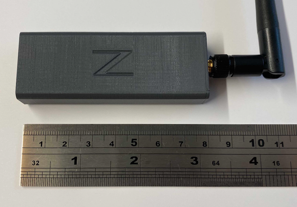
You can also get a complete Z2T module with case, pre-flashed and ready to configure and deploy.

Prototype
C. Flash a DL-20 Zigbee module The DL-20 Zigbee module has a 5-pin 1.27mm pitch unpopulated header with 0.6mm througholes. For flashing any of the Zigbee modules, you need the following connections:
| ESP Pin |
D1 Mini NodeMCU |
CC2530 Pin |
DL-20 J2 Pin Location |
|---|---|---|---|
| GPIO12 | D6 | CC_DD (A.K.A. P2_1 ('P21') or Debug Data) |
5 |
| GPIO4 | D2 | CC_DC (A.K.A. P2_2 ('P22') or Debug Clock) |
4 |
| Vcc | 3.3v | Vcc | 3 |
| GPIO5 | D1 | CC_RST | 2 |
| GND | GND | GND | 1 |
DL-20 Flashing Jumpers
Insert alternating male Dupont jumpers; one jumper on one side, the next one on other side. This allows the pins to provide the friction themselves to maintain contact and remain firmly in place. You only need DD, DC, and RST (a fourth jumper is shown which is used to keep the RST jumper in place). Vcc and GND are available on the main serial interface pins.

D. Upload the firmware to the CC2530
The CC2530 requires Z-Stack_Home_1.2, of type Default (not Source Routing). For convenience, ready to use firmware files are provided. Select the right one for your hardware: CC2530, CC2530 + CC2591 or CC2530 + CC2592.
These Python scripts require Python 2.7.
-
Ensure that you have Python 2.7 installed
-
Install pyserial 3.0.1:
pip install pyserial==3.0.1 -
Check for connectivity before flashing:
python Python/cc_info.py -p <serial_port>where <serial_port> is the serial port for the ESP82xx device. e.g.
/dev/cu.usbserial-xxxxorCOM7Example of result:
INFO: Found a CC2530 chip on /dev/cu.usbserial-xxxx

Chip information:
      Chip ID : 0xa524
   Flash size : 16 Kb
    Page size : 2 Kb
    SRAM size : 1 Kb
          USB : No

Device information:
 IEEE Address : 000000000000
           PC : 0000

Debug status:
 [ ] CHIP_ERASE_BUSY
 [ ] PCON_IDLE
 [X] CPU_HALTED
 [ ] PM_ACTIVE
 [ ] HALT_STATUS
 [X] DEBUG_LOCKED
 [X] OSCILLATOR_STABLE
 [ ] STACK_OVERFLOW

Debug config:
 [ ] SOFT_POWER_MODE
 [ ] TIMERS_OFF
 [ ] DMA_PAUSE
 [ ] TIMER_SUSPEND
If your CC2530 is DEBUG_LOCKED, then the flash size will be incorrectly reported as 16kB. Dont worry flashing the Z-Stack firmware will work and reset the DEBUG_LOCKED bit.
In some situation flashing fails with a error message
flash have not enough space. If this happens do the following:python Python/cc_read_flash.py -p <serial_port> -o x.hex python Python/cc_write_flash.py --erase -p <serial_port> -i x.hexRecheck for connectivity and the correct flash size by repeating step #3.
-
Flash the Z-Stack firmware using the following command:
Flashing the CC2530 takes about 20 minutespython Python/cc_write_flash.py -e -p <serial_port> -i Bin/CC2530_DEFAULT_20190608_CC2530ZNP-Prod.hexINFO: Found a CC2530 chip on /dev/cu.usbserial-xxxx Chip information: Chip ID : 0xa524 Flash size : 256 Kb Page size : 2 Kb SRAM size : 8 Kb USB : No Sections in Bin/CC2530_DEFAULT_20190608_CC2530ZNP-Prod.hex: Addr. Size -------- ------------- 0x0000 8176 B 0x1ff6 10 B 0x3fff0 1 B 0x2000 239616 B This is going to ERASE and REPROGRAM the chip. Are you sure? <y/N>: y Flashing: - Chip erase... - Flashing 4 memory blocks... -> 0x0000 : 8176 bytes Progress 100%... OK -> 0x1ff6 : 10 bytes Progress 100%... OK -> 0x3fff0 : 1 bytes Progress 100%... OK -> 0x2000 : 239616 bytes Progress 100%... OK CompletedIf you don't see any on screen activity that flashing has begun (i.e., progress percentages increasing) within a couple minutes, then abort the command, cycle power on the ESP82xx, and start this step over.
Additional References:
- Flashing with a Wemos D1 Mini or equivalent and
CCLibis described in greater detail in this blog post. - Koen Kanters Z-Stack CC2530 firmware files.
- There are many tutorials online on how to flash a CC2530 with a dedicated CC_DEBUGGER.
Once the CC2530 flashing process completes, you can re-use that ESP82xx device by flashing it with the Zigbee2Tasmota firmware. Otherwise, you can use any ESP82xx device.
- Compile Tasmota
#define USE_ZIGBEEinuser_config_override.h.- optional Run the ESP at 160MHz instead of 80MHz, this ensures higher reliability in serial communication with CC2530.
Inplatformio_override.ini- Uncomment:
board_build.f_cpu = 160000000L
- Uncomment:
[!WARNING] If you find that your Zigbee2Tasmota operation is unstable, you may have an ESP82xx device that cannot operate reliably at the higher frequency. If you are using hardware serial (see below) and you still have unreliability, try compiling for 80MHz (reverse the options above) and flash the ESP82xx device again to see if operating at a lower frequency improves stability. Running at 80MHz will impact software serial communications so hardware serial is highly recommended if running the ESP82xx at 80MHz.
- Follow the usual Tasmota flashing process
The connection uses a 115200 baud serial connection. Hence you need to configure two GPIOs: Zigbee TX and Zigbee RX.
If you are using your ESP82xx device to flash the Zigbee adapter as described in the flashing section, GPIO4, GPIO5, and GPIO12 are already in use. You may want to leave these connections in place in case you need to update the CC2530 firmware in the future. Otherwise, any of these GPIO can also be used.
The interface between the ESP82xx Wi-Fi device and the CC2530 Zigbee module uses high speed serial. It is recommended that hardware serial pins be used (GPIO1/GPIO3 or GPIO13[Rx]/GPIO15[Tx]). Due to ESP82xx GPIO pin constraints, GPIO15 can only be used as serial Tx.
Tasmota also provides serial communications emulation through software (i.e., software serial). This allows any GPIO to be used. TasmotaSerial version 2.4.x (PR #6377) has improved the reliability of software serial making it feasible for use in this application. However, if you have an option to use hardware serial, choose that.
?> Z2T uses software serial by default to allow for serial logging on GPIO1/GPIO3. Use SerialLog 0 to enable hardware serial on GPIO13[Rx]/GPIO15[Tx].
Recommended connections:
| ESP Device |
Tasmota Component |
CC2530 |
|---|---|---|
| GPIO13 | Zigbee RX (166) | CC_TXD (A.K.A. P0_3) |
| GPIO15 | Zigbee TX (165) | CC_RXD (A.K.A. P0_2) |
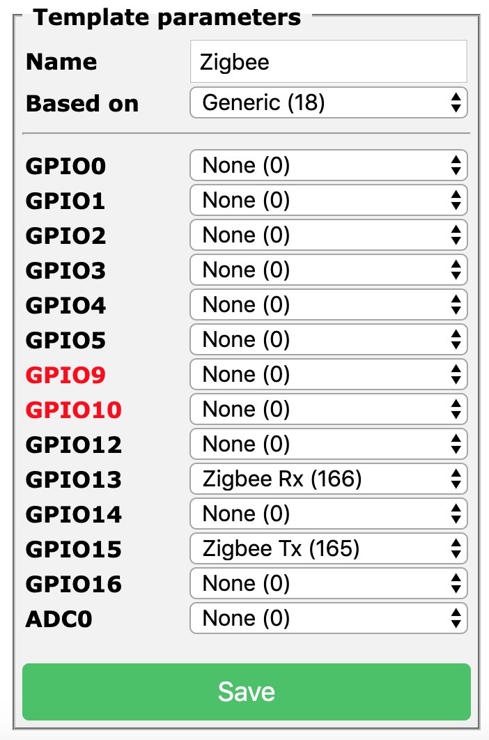
Configure the Tasmota device using a custom template. Assign Zigbee Tx (165) and Zigbee Rx (166) to the corresponding GPIOs to be used for serial communication with the CC2530. For example:
{"NAME":"Zigbee","GPIO":[0,0,0,0,0,0,0,0,0,166,0,165,0],"FLAG":0,"BASE":18}When the Tasmota device boots, Zigbee2Tasmota will wait for 15 seconds before initializing the CC2530. This time allows for Wi-Fi and MQTT connection (hopefully).
When you first run your CC2530, you will see additional steps to configure the device:
MQT: tele/<topic>/RESULT = {"ZbState":{"Status":1,"Message":"CC2530 booted","RestartReason":"Watchdog","MajorRel":2,"MinorRel":6}}
MQT: tele/<topic>/RESULT = {"ZbState":{"Status":50,"MajorRel":2,"MinorRel":6,"MaintRel":3,"Revision":20190608}}
MQT: tele/<topic>/RESULT = {"ZbState":{"Status":2,"Message":"Reseting configuration"}}
MQT: tele/<topic>/RESULT = {"ZbState":{"Status":3,"Message":"Configured, starting coordinator"}}
MQT: tele/<topic>/RESULT = {"ZbState":{"Status":51,"IEEEAddr":"00124B00199DF06F","ShortAddr":"0x0000","DeviceType":7,"DeviceState":9,"NumAssocDevices":0}}
MQT: tele/tasmota/Zigbee_home/RESULT = {"ZbState":{"Status":0,"Message":"Started"}}
ZIG: Zigbee started
Normal boot looks like:
MQT: tele/<topic>/RESULT = {"ZbState":{"Status":1,"Message":"CC2530 booted","RestartReason":"Watchdog","MajorRel":2,"MinorRel":6}}
MQT: tele/<topic>/RESULT = {"ZbState":{"Status":50,"MajorRel":2,"MinorRel":6,"MaintRel":3,"Revision":20190608}}
MQT: tele/<topic>/RESULT = {"ZbState":{"Status":3,"Message":"Configured, starting coordinator"}}
MQT: tele/<topic>/RESULT = {"ZbState":{"Status":51,"IEEEAddr":"00124B00199DF06F","ShortAddr":"0x0000","DeviceType":7,"DeviceState":9,"NumAssocDevices":0}}
MQT: tele/<topic>/RESULT = {"ZbState":{"Status":0,"Message":"Started"}}
ZIG: Zigbee started
You can also force a factory reset of your CC2530 with the following command, and reboot:
ZigbeeReset 1


