-
Notifications
You must be signed in to change notification settings - Fork 140
Home
Welcome to the ESP32-Serial-Bridge wiki!
ESP32-Serial-Bridge Transparent WiFi (TCP) to all three UART Bridge, supports both AP and STATION WiFi modes. The .ino file is the code for the ESP32 while the header file .h contains all settings for the project. Both files must be placed in the same project folder. Use Arduino IDE for ESP32 to compile and upload it to the ESP32. The project also needs the Library "arduino-esp32" It must be installed in the arduino IDE. https://github.com/espressif/arduino-esp32
How to intall the library can be found via google, for windows this might be the result: https://randomnerdtutorials.com/installing-the-esp32-board-in-arduino-ide-windows-instructions/
It is recomend to start your project with a Node32s or compatible evaluation board.
I made this project in order to connect Flight equipment devices devices like (Radio, Vario FLARM), to a Flight Computer (Kobo, Smartphones etc.), but it is not limited to that. You can use it wherever you want, but on your own risk. Read license file for more details.
After a successful compilation and upload to the ESP32 Module you get a new Accesspoint with the following parameter:
- IPAdress: 192.168.4.1
- AP SSID: LK8000
- AP Password: Flightcomputer
- Used Ports:
- 192.168.4.1:8880 <-> COM0
- 192.168.4.1:8881 <-> COM1
- 192.168.4.1:8882 <-> COM2
In some cases the memorylayout is to small for this scetch. If you face this problem you can either disable Bluetooth by removing #define BLUETOOTH in config.h or change the partition size as described here: https://desire.giesecke.tk/index.php/2018/04/20/change-partition-size-arduino-ide/
example usecases:
https://www.youtube.com/watch?v=K2Hia06IMtk
https://www.youtube.com/watch?v=GoSxlQvuAhg
Hardware:
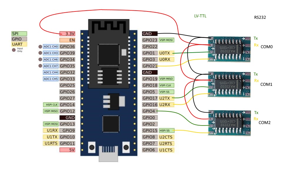
here is the wiring diagram recomendation:

https://raw.githubusercontent.com/AlphaLima/ESP32-Serial-Bridge/master/ESP32-SerialBridge.jpg
Please note that the Mini RS3232 boards have two Rx/Tx drivers. Each board has one on the front one on the back side. So you need only two of the board for the three ports. The Inputs of the unused driver should have a defined potential (Pullup or Pulldown) to prevent unintended oscillations.
Pinning
- COM0 Rx <-> GPIO21
- COM0 Tx <-> GPIO01
- COM1 Rx <-> GPIO16
- COM1 Tx <-> GPIO17
- COM2 Rx <-> GPIO15
- COM2 Tx <-> GPIO04
NOTE: The PIN assignment has changed and may not look straigt forward (other PINs are marke as Rx/Tx), but this assignment allows to flash via USB also with hooked MAX3232 serial drivers.
I recomend to start your project with a Node32s or compatible evaluation board. For a TTL to RS232 level conversion search google for "TTL RS3232 Converter"

Here is an example of an integrated PCB with FLARM compatible RJ45 connectors:
A discussion incl. the similar ESP8266 projekt can be found here:


