Case Balancing Robot 1
Beginner balancing robot developed by CASE Association.
- 1 x Arduino Nano
- 1 x TB6612FNG (DC motor driver)
- 1 x MPU6050 (Inertial measurement unit)
- 1 x CBR-1 3D-printed chassi
- 2 x 6V DC motors (with wheels)
- 1 x Rockerswitch or other switch (between 9V battery and PCB)
- 1 x 4xAA batteryholder
- 1 x 9V batteryholder
- 4 x M3x10 screw (M3x12 might also work)
- 4 x M3 nut
- Wires
- Heatshrink
- 4 x AA batteries (there are some in the lab you can try out with your bot with but it's a good idea to bring your own batteries)
- 1 x 9V battery (same with AA batteries, it's nice to bring your own)
Optional:
- 1 x Rockerswitch or other switch (now between the 4xAA batteryholder and PCB)
- 2 x LED
- 2 x Resistors R1 and R2
- Various pin-connectors For R1 and R2, use whatever resistance you prefer for LEDs in these applications, but around 300 ohm works fine. We used 100 Ohm for a red LED and 300 Ohm for a blue LED.
All of the components are available to purchase in the iZettle, but feel free to use your own components if you for instance want a more powerful battery to power the motors. The most important thing is that you are able to supply 9-12 V to the Arduino and at least 6 V to the motors (a somewhat higher voltage will work, you'll get more power!). Using 4xAA (4 in series) is the absolute minimum battery solution, considering the max current you get from them.
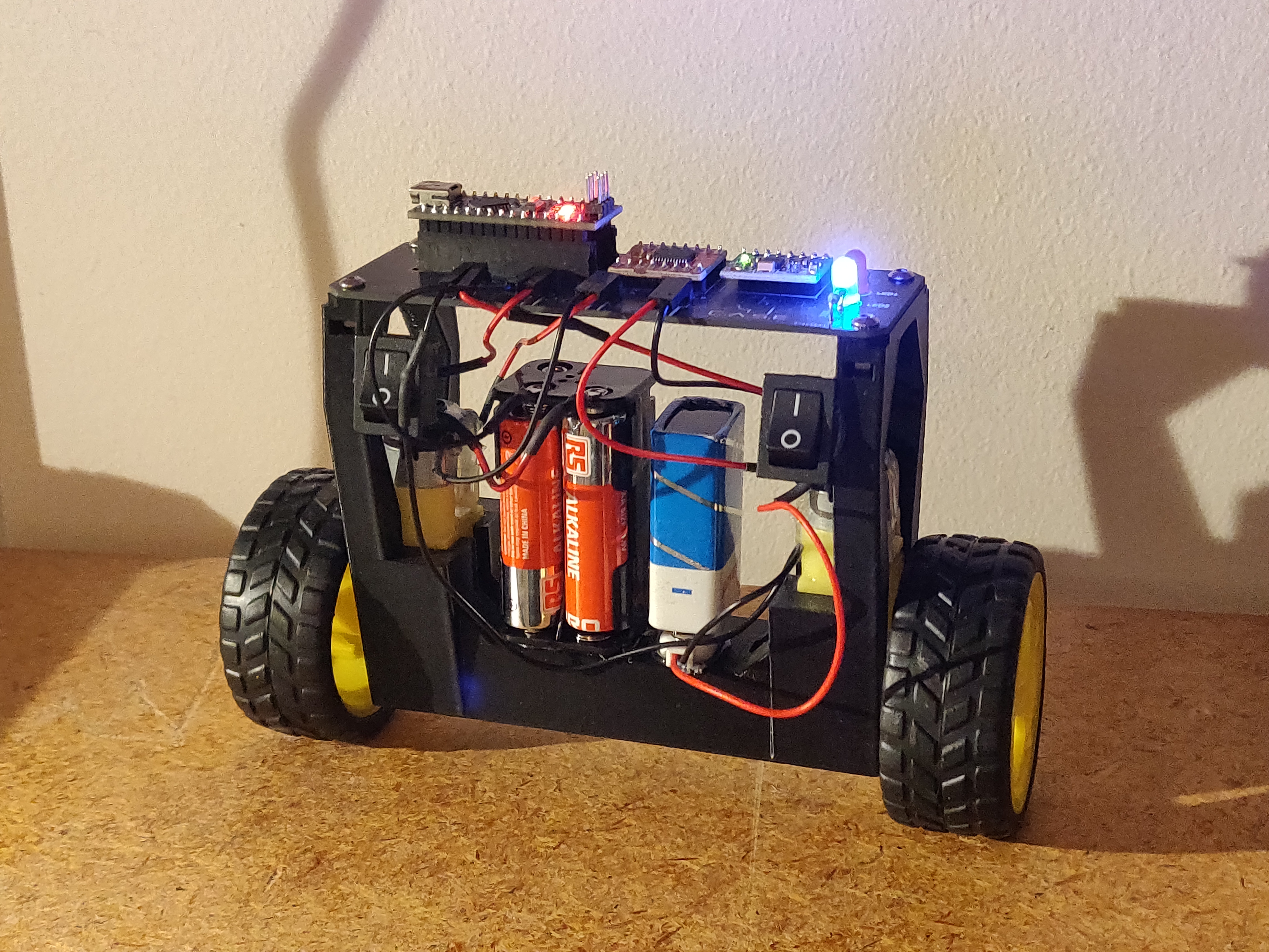
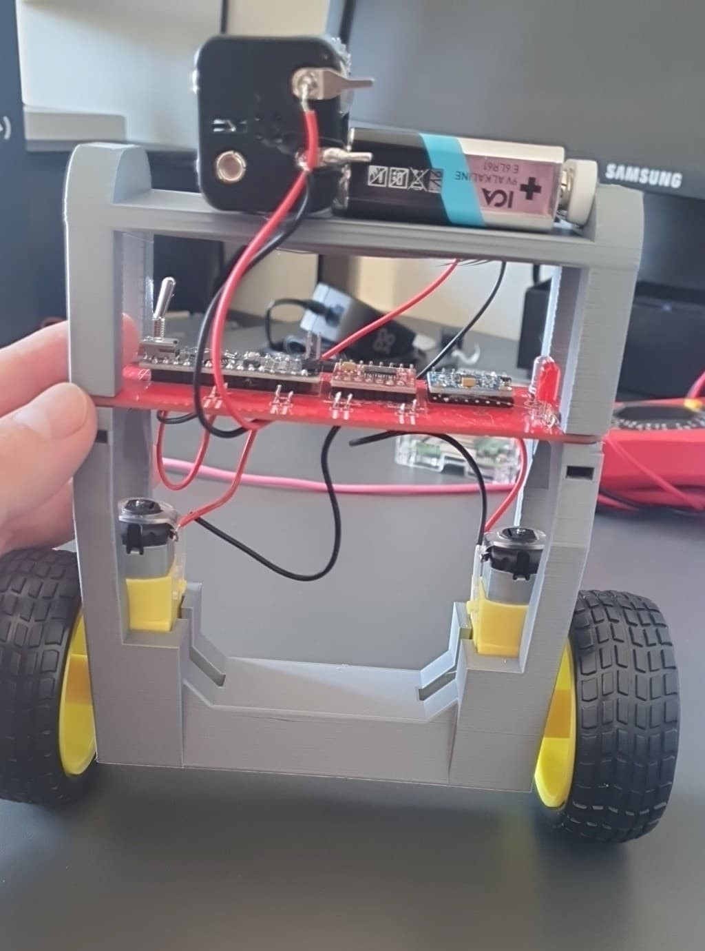
The 3D-printed chassi can, if not bought through iZettle, be redesigned and 3D-printed if you like. The STL file is provided in the CAD folder, and you can also design things to add to the robot! The picture below shows an example of a way to increase the distance between the ground and the centrum of mass by placing the batteries on top. This makes it easier for the robot to balance!
The STL file for this extra piece can also be found in the CAD folder.
There's quite a bit of it.
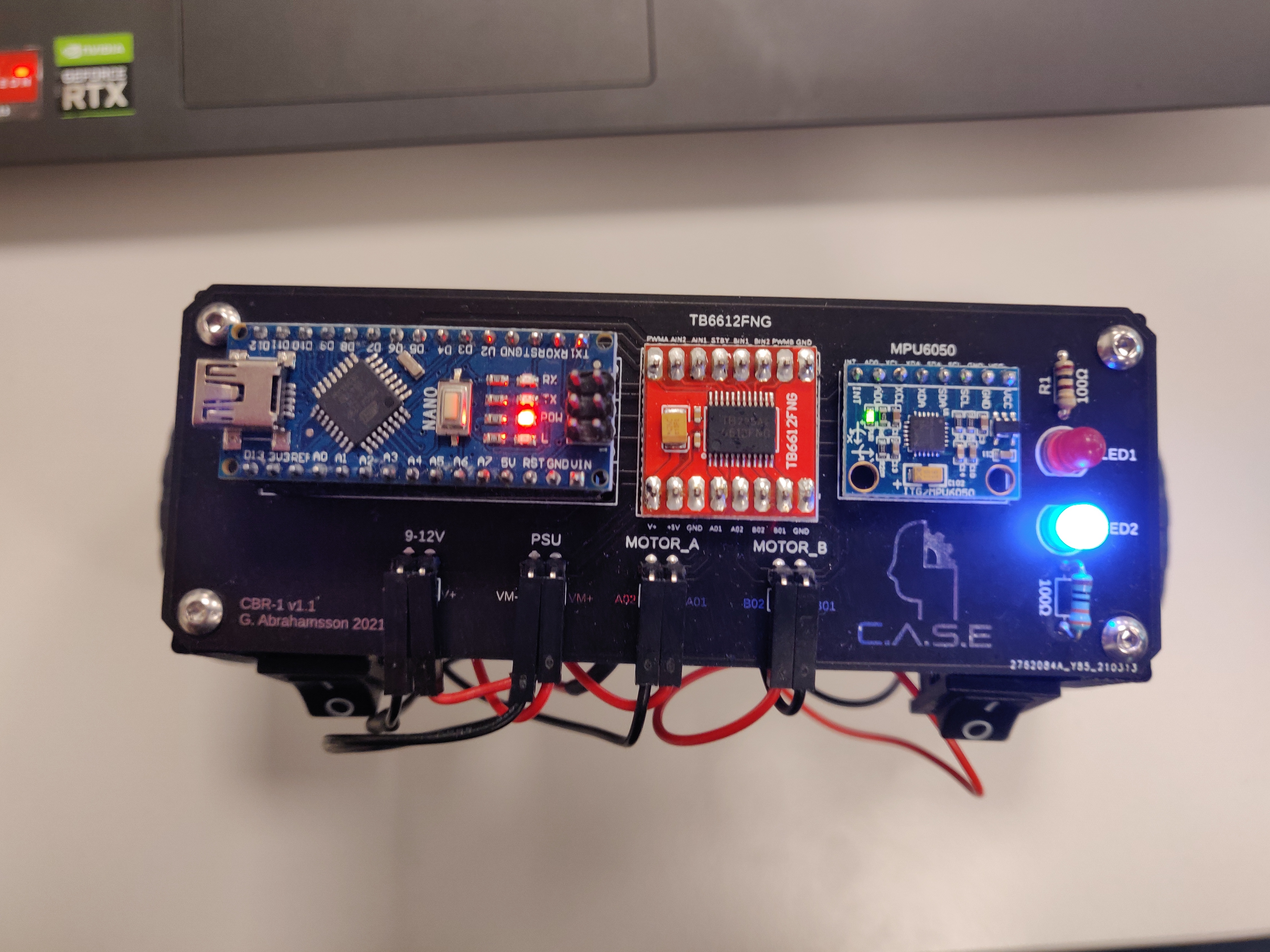
The three main components to solder to the PCB are:
- Arduino Nano
- TB6612FNG
- MPU6050
The PCB is marked where to attach each component, but you can solder in two ways:
This gives the most clean look, but can be quite troublesome if something goes wrong. It's very important that you orient the components in the correct way (they fit both ways, but only one works)! Double check that the ports on the components match the ones on the PCB before soldering.
Solder female pin connectors to the PCB and then attach your components to them. This way you can reuse components if you don't feel like buying the same component for another project in the future. If a component fails, you can also replace them much easier.
If you want LEDs on your robot, solder them to the PCB with their respective resistor. Don't forget that LEDs are Light Emitting Diodes.The kathode (the shorter pin) must be put into the hole near the "flat side" of the footprint on the PCB. The anode (the longer pin) must be put into the hole near the "round side".
Don't forget heatshrink before you solder!
Connectors can be soldered to the ports for 6-12 V, powersupply (marked "PSU" or "6V"), motor A and motor B if you like. This makes it easier to detach parts of the robot without needing to desolder anything. In the example on page 1, 90° male pin connectors are used on the PCB while the motors and batteries all have female pin connectors soldered to their respective cables.
If you only want to use one switch, use it with the 9V battery. This ensures that the only switch used is turning the Arduino Nano on/off (since the 9-12V port is powering the Nano and PSU/6V is powering the motors). The switch can be between the battery and the positive or the negative pin on the PSU/6V ports, since it's breaking the circuit. We soldered the already attached red wire from the 9V battery to one pin on the switch, and then another wire (dupont-cable with one end cut off) on the other pin on the switch. Another dupont cable was soldered to the other wire from the battery holder to make sure it has a female connector.
The same was done with the 4xAA battery holder, but the wires were soldered to the pins since this particular battery holder does not come with wires already attached.
Repeat this for the other pack, but ignore the switch if you do not want to use two of them. Remember, having control over both batterypacks while the robot is in action is very helpful. We recommend two switches!


When soldering wires to the batterypacks, don't forget to use red for positive and black for negative! Things get very problematic if they are mixed up!
For each motor, solder wires to each of the connections on the motor. Heatshrink is good to use here (don't for get to put it on before you solder!), and applying some hot glue around the connection after everything is done will decrease the risk of the copper breaking from bending. Also, using dupont cables with female pin connectors is a fast way to get wires without having to attach connectors to the end of the wires. Just cut one end off and keep the other!
If the wheels aren't already attached, attach them now.
Bring out the glue gun!
Everything except for the PCB is attached with hot glue, so just glue on the motors and batterypacks! Remember not to orient the packs in a way where you can't remove/attach batteries.
Drop in an M3 nut in each hole and screw on the PCB with the M3 screws. It's possible to glue the PCB to the chassi but it's made to be assembled with nuts and screws.
If you're not using connectors, replace "connect" with "solder":
- Connect the wires from the 9V battery holder to the 9-12V port.
- Connect the wires from the 4xAA battery holder to the PSU/6V port.
- Connect the wires from one of the motor to the "Motor A" port. It does not matter which wire goes to which pin, this can be corrected in the code if the motor turns the wrong way.
- Connect the wires from the other motor to the "Motor B" port.
The robot is now fully assembled!
PlatformIO was used for this project. The code can be found in the "Code" folder.
The following libraries are needed:
- PID_v1.h
- I2Cdev.h
- MPU6050_6Axis_MotionApps20.h
Make sure they are in your project!
Upload the code to the Nano. Do not freak out if it doesn't work at first! There's a few things that might need to be adjusted.
When tilting the robot to one direction, the motors should turn in a way that drives it in that direction. If a specific motor does not turn that direction, you can switch the connectors. This will switch the direction the motor turns. Do this to both motors so that they drive in the direction the robot tilts.
If you do not have connectors, but have soldered the wires to each port, you can switch the direction of the motors in the code. This is done by changing the LOW to HIGH or HIGH to LOW of both ports on a specific motor in the functions Forward and Reverse. Having in1A LOW and in2A HIGH will rotate the motor in one direction, and switching in1A to HIGH and in2A to LOW will make it rotate the other direction.

You can achieve the same effect by switching the output from negative to positive or vice versa:
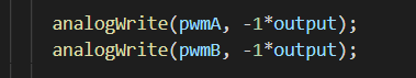
The robot might not perform optimally with the default values included. This will be fixed here.
If the robot is trying to escape everytime you set it down, you might have to calibrate the setpoint. If it's too low or too high, the robot will correct itself to a too low of an angle, making it tilt and therefore accelerating in that direction.
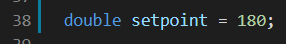
Problems with the setpoint can also occur if the MPU6050 is not soldered/connected parallell to the PCB. If you feel comfortable trying to bend it parallell, go ahead, but adjusting the setpoint in the code also works.
If the robot isn't balancing, or trying too violently, you can adjust the PID values (especially if you've attached the batteries in another way compared to ours at the top of this page!).
Start by adjusting the Kp value. This affects the output based on the difference from the measured and target value. If it's too slow or "weak", increase the value. If it's too violent and jerky, decrease the value.
After that, move on to Kd. This affects the output based on the derivative. If it's too jittery, reduce the value.
Lastly, adjust Ki. This affects the output based on the integral. Start from a low value and increase it until it works.
It should now balance on its own!
You can control the LEDs (if you have them) by writing a 1 or a 0 to their respective ports:
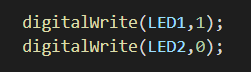
In the provided code, the LEDs will show which direction the robot is currently travelling in.
There's a lot about this robot that can be improved. Here's a list of things to improve if you'd like:
- 3D-printed chassi: Design your own chassi or some piece to be attached to it! The center of mass needs to get higher!
- Code that takes velocity into concideration: Currently, the robot is satisfied as long as it's standing upright, even if its travelling at max speed. Try to fix this in the code!
- Improved PCB: If you're into SMD, you can design a PCB with no throughhole components and only surface mounted ones. It will look much cooler!
- Wireless controls: You could attach for instance an NRF24L01 to enable wireless communication with a controller!
- Other batteries: It is possible to use for instance LiPo batteries to enable more power, while also only needing one battery.
- Measure the angle that the motors rotate to: Since regular DC motors and no stepper motors (or something similar) are used in this project, the robot does not know how much the wheels have actually rotated. It is possible to use sensors to measure this and to use the information in conjunction with the controls-code.