Warning
KAMP aka Klipper-Adaptive-Meshing-Purging should be removed from your klipper prior to using Eddy. Please comment out the include line. ie #[include ./KAMP/adaptive_meshing.cfg] from your KAMP_SETTINGS.cfg
Instead KAMP has been integrated into klipper as of January 2024 and you should use the ADAPTIVE=1 option in your BED_MESH_CALIBRATION calls. You can find more Information on Adaptive Mesh Here
Warning
As it stands, Eddy requires the use of BTT's fork of klipper found HERE. This is included in the guide under steps 13.
This will be merged into mainline klipper at some stage and the guide will be updated once it happens. Until then this is a STRICT REQUIREMENT.
Please read NOTES
- Compiling Firmware
- Printer Configuration
- Live Current Calibration
- Z-Offset Calibration
- Bed Mesh Calibration
- Temperature Compensation Calibration
- Bed Mesh Calibration Parameters
- Bed Mesh Scan Height
- Bed Mesh Rapid Scanning
- Extras & Notes
-
- Includes Print Start Macro Adjustment
- FAQ - Frequently Asked Questions
- Known Issues
-
- BTT Knomi
- SSH into raspberry PI
- Type
cd ~/klipper
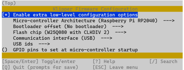
make menuconfig
- Use these settings to compile the firmware.

- Once set, hit 'Q' and when asked, select yes to save.
- Type
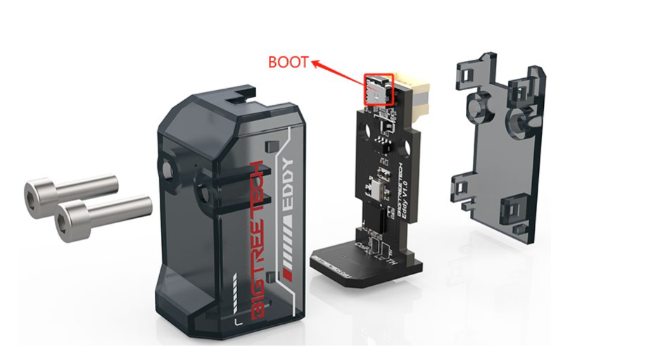
maketo compile. - Disconnect power to Eddy
- Push and hold boot button on Eddy (Its next to where the cable plugs in) and at the same time, plug in the cable to your Raspberry Pi

- SSH into raspberry Pi
- Type
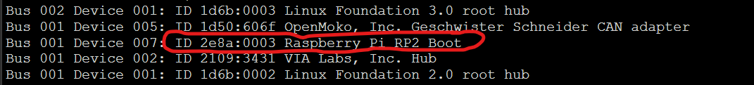
lsusbinto the command line. You should see eddy.
- Type
cd ~/klipperinto command line - Type
make flash FLASH_DEVICE=2e8a:0003Remember to change 2e8a:0003 to your device ID you found in step 9 - Type
ls /dev/serial/by-id/*into the command line. The found device will be what you enter into your klipper config under [mcu eddy] for the Serial variable.
Note
You need to change from the main branch of klipper to BTTs branch as discussed in the warning at the top of the page. This is only temporary and will be updated accordingly.
Still accurate as of 13-05-2024.
- Change to BTT klipper by entering the following via SSH
git remote add eddy https://github.com/bigtreetech/klipper
git fetch eddy
git checkout eddy/eddy
- Type into command line
sudo reboot
Important
If you want to enable Z-Homing/Endstop, under your [stepper_z] in printer.cfg change endstop_pin: PA5 to endstop_pin: probe:z_virtual_endstop and comment out or remove position_endstop: 0
- Add the following to your printer.cfg making sure to adjust for your bed size and probe position
Important
Adjust your x_offset and y_offset to match your probe position relative to your nozzle. You can do that following these steps found HERE
[mcu eddy]
serial: /dev/serial/by-id/usb-Klipper_rp2040_4550357129142D58-if00

[temperature_sensor btt_eddy_mcu]
sensor_type: temperature_mcu
sensor_mcu: eddy
min_temp: 10
max_temp: 100

[probe_eddy_current btt_eddy]
sensor_type: ldc1612
z_offset: 1.0
#i2c_address:
i2c_mcu: eddy
i2c_bus: i2c0f
x_offset: 0 # Set according to the actual offset relative to the nozzle
y_offset: 20 # Set according to the actual offset relative to the nozzle
data_rate: 500

[temperature_probe btt_eddy]
sensor_type: Generic 3950
sensor_pin: eddy:gpio26
horizontal_move_z: 2

[bed_mesh]
horizontal_move_z: 2
speed: 300
mesh_min: 10, 10
mesh_max: 220, 220
probe_count: 9, 9
algorithm: bicubic


[safe_z_home]
home_xy_position: 125, 125
z_hop: 10
z_hop_speed: 25
speed: 200
- Place Eddy Approx. 20mm above the bed.
- From Mainsail or Fluidd run command
LDC_CALIBRATE_DRIVE_CURRENT CHIP=btt_eddy - Type
SAVE_CONFIGto save the drive currant to your config
Important
If using a printer with Quick Gantry Leveling (Voron etc) perform it now to ensure the gantry is level and to prevent the nozzle rubbing into the bed.
- Home X and Y axes with command
G28 X Y - Make sure you dont have a bed heightmap loaded.
- Move Nozzle to Centre of the bed with
G0 X125 Y125 F6000(adjust for your bed size) - Start Manual Z-Offset Calibration by typing
PROBE_EDDY_CURRENT_CALIBRATE CHIP=btt_eddy(TIP: Go a little lower than you normally would)
Important
Perform another Quick Gantry Leveling (Voron etc)
- Once completed use
SAVE_CONFIG
- Home All Axes
- Use command
BED_MESH_CALIBRATE METHOD=scan SCAN_MODE=rapidParameters - Once completed use
SAVE_CONFIG
Caution
The following steps (27-36) are for Eddy USB Only. Eddy Coil doesnt have temperature compensation so these steps should be disregarded.
- Home All Axes and move Z 10 above bed
- Set idle timeout
SET_IDLE_TIMEOUT TIMEOUT=36000 - Record ambient temp of the BTT Eddy Sensor

- Set max temp for bed (i.e 100c) and set typical temperature for hotend (200c)
- Wait for BTT Eddy temp to stabilize then record temp.
- Return to room temp by turning off bed and hotend

Tip
If you have a high range to test between ambient and max eddy temp from step 25, you can change the value of STEP=3 to STEP=5 to save you some time. Ideally you want as many calibration points as possible for the best use of eddy but I found for range between 30c-50c a STEP value of 3 was sufficient
- Run
PROBE_DRIFT_CALIBRATE PROBE=btt_eddy TARGET=50 STEP=3(target should be the temp you recorded of the max recorded temp from step 31. - Using the paper method adjust your Z offset.
- Turn on your heat bed and nozzle to same values as step 30
- As Eddy temp rises at each 3c (STEP=3) increment, you will automatically be asked to set the z-offset when prompted using the paper test.
Note
By default the calibration procedure will request a manual probe every 2C between samples until the TARGET is reached. The temperature delta between samples can be customized by setting the STEP parameter in PROBE_DRIFT_CALIBRATE.
The following additional gcode commands are available during drift calibration.
PROBE_DRIFT_NEXT may be used to force a new sample before the step delta has been reached.
PROBE_DRIFT_COMPLETE may be used to complete calibration before the TARGET has been reached.
ABORT may be used to end calibration and discard results.
Tip
You might not reach your target temperature, thats okay. You can end the test by using command PROBE_DRIFT_COMPLETE to finish.
- Youre all done! :)
Make sure you LIVE ADJUST your z-offset with your first print to really home it in.
Some probes, such as Eddy, are capable of
"scanning" the surface of the bed. That is, these probes can sample a mesh
without lifting the tool between samples. To activate scanning mode, the
METHOD=scan probe parameter should be passed in the BED_MESH_CALIBRATE
gcode command.
To accommodate these probes the following additional probe_parameters are
available to BED_MESH_CALIBRATE:
SCAN_MODE=[detailed | rapid]: Choses the scan mode. Thedetailedmode will pause and collect samples at each probe point. Therapidmode will travel on a continuous path with no pauses, collecting samples near each probe point.SCAN_SPEED=[speed]: The maximum X/Y travel velocity of the tool when performing a scan. The default is the value of thespeedoption in the configuration.SAMPLE_TIME=[time]: The time, in seconds, the tool pauses for sample collection indetailedscan mode. The default is .1 seconds.SAMPLES_RESULT=[option]: The type of averaging to perform on collected samples. Available options are:standard: All collected samples are averaged.centered: Samples are sorted by value. The first and last quarters are discarded and the remaining samples are averaged.weighted: Samples closer to the desired probe location are assigned more weight in the average than samples farther from the location.
The scan height is set by the horizontal_move_z option in [bed_mesh]. In
addition it can be supplied with the BED_MESH_CALIBRATE gcode command via the
HORIZONTAL_MOVE_Z parameter.
The scan height must be sufficiently low to avoid scanning errors. Typically
a height of 2mm (ie: HORIZONTAL_MOVE_Z=2) should work well, presuming that the
probe is mounted correctly.
It should be noted that if the probe is more than 4mm above the surface then the results will be invalid. Thus, scanning is not possible on beds with severe surface deviation or beds with extreme tilt that hasn't been corrected.
When performing a rapid scan one should keep in mind that the results will
have some amount of error. This error should be low enough to be useful on
large print areas with reasonably thick layer heights. Some probes may be
more prone to error than others.
It is not recommended that rapid mode be used to scan a "dense" mesh. Some of the error introduced during a rapid scan may be gaussian noise from the sensor, and a dense mesh will reflect this noise (ie: there will be peaks and valleys).
Bed Mesh will attempt to optimize the travel path to provide the best possible result based on the the configuration. This includes avoiding faulty regions when collecting samples and "overshooting" the mesh when changing direction. This overshoot improves sampling at the edges of a mesh, however it requires that the mesh be configured in a way that allows the tool to travel outside of the mesh.
[bed_mesh]
speed: 120
horizontal_move_z: 5
mesh_min: 35, 6
mesh_max: 240, 198
probe_count: 5
scan_overshoot: 8
scan_overshootDefault Value: 0 (disabled)
The maximum amount of travel (in mm) available outside of the mesh. For rectangular beds this applies to travel on the X axis, and for round beds it applies to the entire radius. The tool must be able to travel the amount specified outside of the mesh. This value is used to optimize the travel path when performing a "rapid scan". The minimum value that may be specified is 1. The default is no overshoot.
If no scan overshoot is configured then travel path optimization will not be applied to changes in direction.
- Add the following to your start print macro to enable adaptive bed mesh using Eddy
BED_MESH_CALIBRATE SCAN_MODE=rapid METHOD=scan ADAPTIVE=1
- Make sure you are using the correct macro call.
BED_MESH_CALIBRATE SCAN_MODE=rapid METHOD=scan - Remove or alter KAMP - Adaptive Bed Mesh and any custom BED_MESH_CALIBRATE macros. Use klipper adaptive mesh instead or alternatively do not include KAMP/Adaptive_Meshing.cfg in your KAMP_Settings.cfg Information on Adaptive Mesh Here
-
BTT Knomi will cause z-hops, please edit you KNOMI.CFG specifically this line.
SET_GCODE_VARIABLE MACRO=_KNOMI_STATUS VARIABLE=probing VALUE=True
BTT_BED_MESH_CALIBRATE
SET_GCODE_VARIABLE MACRO=_KNOMI_STATUS VARIABLE=probing VALUE=False
so that it looks like this
SET_GCODE_VARIABLE MACRO=_KNOMI_STATUS VARIABLE=probing VALUE=True
BTT_BED_MESH_CALIBRATE SCAN_MODE=rapid METHOD=scan
SET_GCODE_VARIABLE MACRO=_KNOMI_STATUS VARIABLE=probing VALUE=False
- It depends on your needs. Eddy USB and Eddy Coil are nearly identical, however Eddy Coil is more for toolhead boards and connects via I2C connectors.
- Eddy Coil cannot be used for z-homing as a z-endstop as it doesnt feature temperature compensation.