MAF Based Design.
You may think that simply wiring up a MAF to an arduino and installing it in a length of pipe is all that you need to do. In a way it is, but there are some caveats to doing this. To get the best results, i.e. the most accurate and repeatable results, you need to consider how the air flows inside your flow bench and design your bench so that the MAF sensor is not influenced by disruptions to the airflow.
Depending on what type of MAF sensor you are using you may need to increase the length of straight tube before and after the MAF. This is to prevent turbulence affecting the measurement. This is not an issue with slot style MAF sensors due to the way that they work, but can be an issue with regular MAF sensors. Generally most sensors integrate some form of honeycomb air straightener to reduce this turbulence prior to measurement. Some newer sensors are designed in a way that minimises the affect of turbulence on the reading.
The distance that it takes for the flow to become 'fully formed', i.e. non-turbulent, is known as the entrance length, this represents the length from the entrance to the pipe section that the flow takes to settle. In this application this is essentially the distance between the head and the MAF sensor. you can accurately calculate this but you will often see it expressed in terms of diameters. You will see many figures quoted for this (40 diameters / 10 diameters / etc) most are anecdotal but generally all of which are impractical to implement due to space limitations.
Car manufacturers also have these same limitations, so they have overcome them by adding flow straighteners to reduce this distance. Newer slot style sensors are designed in such a way that they are less susceptible to flow disruptions and do not require flow straighteners. This helps obtain more stable and accurate readings in a much smaller distance. However, even with these styles of sensors, there is still value in maximising the straight section of pipe entering and exiting the MAF. If you have the space in your design it is worth considering that a long straight section before and after the MAF will help stabilise readings.
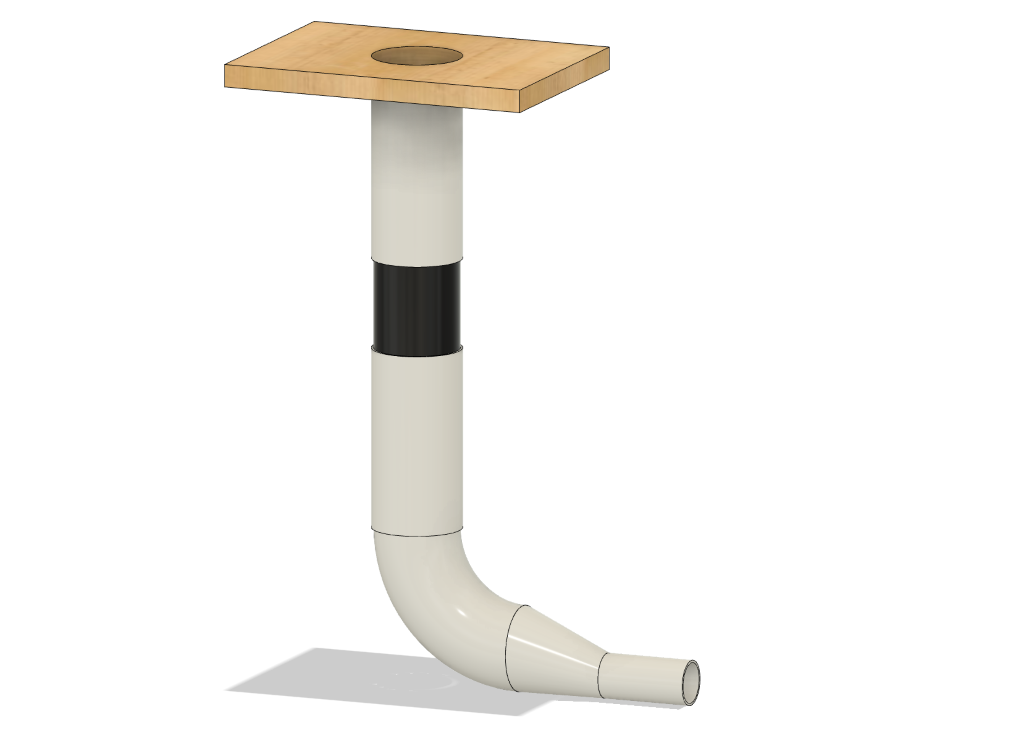
Here is a good general design which will fit in a 900mm tall bench (as shown in image above):
From top to bottom
- Use the same diameter pipe as your MAF.
- 400mm long 100mm section between MAF sensor and the test piece
- Rubber connector
- MAF sensor
- Rubber connector
- 300mm long 90mm section between MAF sensor and Vac source
- Adding a 90 degree fitting before the vac source will help remove turbulence / vortices
- Eccentric reducer into long 50mm section connected to a high powered Shop-Vac unit
NOTE: Using a slot style MAF requires a single length of any diameter tube. The published MAF flow data can be transposed for other pipe diameters automatically within the software.
Of course you can get much more fancy than this, but it is a quick and easy bench to build and will give you reasonable results. The main limiting factor is the vacuum source
In its simplest form you can use a regular shop vac as your vacuum source. This does have some limitations as it will only flow a finite amount of air.
If your heads outflow your vac, then flow readings from higher valve lifts will all appear to be the the same. This is because the flow reading will basically showing the maximum flow of the vac unit and not the flow of the head itself. Ideally your vac source needs to be able to provide a minimum of 120% of your expected flow.
You might also want to consider adding some form of vacuum bleed off so that you can bleed off excessive vacuum in the case of testing small or restrictive items. Using a bleed valve will also allow you to dial in specific test depressions. Provided of course that your vacuum source generates enough vacuum to support this.
If you want to flow higher numbers than a shop vac can produce, then you are probably looking at building your own vac source. This generally involves integrating multiple vacuum cleaner motors within a plenum box that can then be connected to the flow bench. The Vac Motor Selection section helps you to determine what motors you will need and how many.
Consideration to how you can reverse the bench operation from vacuum to pressure for testing exhaust port flow is also a factor in your design. If you are just using a simple shop vac setup then you will need to make sure that it has both a 'Vac' and a 'Blow' port that can be connected to.
If you are using a slot style MAF, this can simply be rotated in the housing to reverse the measurement direction, however for fixed style MAF sensors you will need to physically swap it.
If you are building a large separate vacuum source, it is worth considering making it with a pressure port on one end and a vacuum port on the other so that the bench can be easily and quickly swapped between operations. If you are building an all-in-one integrated plenum design bench you will need to use some form of flow management with flaps or sliding dividers inside to direct the flow as necessary.
You can also 'cheat' by connecting the exhaust port to the test surface so that instead of blowing out of the exhaust valve from within the cylinder and requiring you to reverse the flow of the bench, you suck air through the exhaust port from the exhaust side. This is most easily achieved by using a 90 degree pipe fitting connected to the test surface that is in turn connected to the exhaust port. Using an exhaust stub pipe bolted to the head makes this simple to set up.
Of course, the keyboard warriors amongst you will say that sucking the air through the exhaust port instead of blowing it through does not give a true reading, but the actual difference is negligible. There is a far greater difference between the ambient air used by your test bench and the 300 deg+ air created by your engine. Remember not to lose sight of the fact that a flow bench is never going to mimic the actual conditions seen in an engine, it's simply a tool to help you quantify improvements that you make.
The business end of the bench is where you attach your test object to be measured. If you are testing a cylinder head, it is important that you mimic the cylinder beneath the head as it has a large influence on the flow characteristics. You also need to make sure that the bench inlet (the hole that you place your test object over) is of a suitable size to accommodate the typical range of heads and cylinder sizes that you may encounter.
110mm waste pipe is a perfect size that will accommodate most modern production vehicles. From go karts and motorcycles right up to small block chevy. This allows you make up interface plates that have a tube of the correct diameter to represent your cylinder. The tube will slide neatly inside the much larger 110mm pipe. If you need a pipe diameter of this size then it is worth starting off with a MAF of this size too as the reduction in pipe diameter between the test piece and the MAF may introduce some turbulence and affect readings.
The test surface should also ideally be flat and large enough to safely support the weight of the cylinder head as well as be able to provide a seal between the bench surface and any adaptor used.
If you can find some, clear tube is the ultimate material. You can view the inside of the cylinder which allows you to see how the airflow behaves entering the cylinder by using flow probes in the inlet port. Often an adaptor stand will be used that raises the cylinder head up off of the test surface. This integrates a tube to mimic the cylinder. Making this part from clear tube will help you to see what's happening inside the combustion chamber around the valves using flow wands.
To ensure that the reference pressure used is constant between readings you can fit an air bleed to the vacuum pickup pipe. This allows you to control a small opening to meter the amount of air bled into the system. Allowing air into the system will lower the reference pressure allowing you to dial it in to the desired value. You can create a simple air bleed by installing a tee piece with a capped-off end that has holes drilled around the edge. Rotating the cap exposes the holes.
You can also use the fan speed output to control the fan speed using a VFD or other type of speed controller. There is also an automated air bleed output that you can use to operate a control valve to automatically meter the reference pressure. <(V3) The air bleed can be used in conjunction with set fan speeds or several fans operated in sequence.
The WebUI currently provides basic on/off controls for the bench. The ESP32 GPIO's can be used with a relay module to control the power to your vac motors.
Future updates will include batch fan control as well as VFD fan speed and PWM bleed valve control