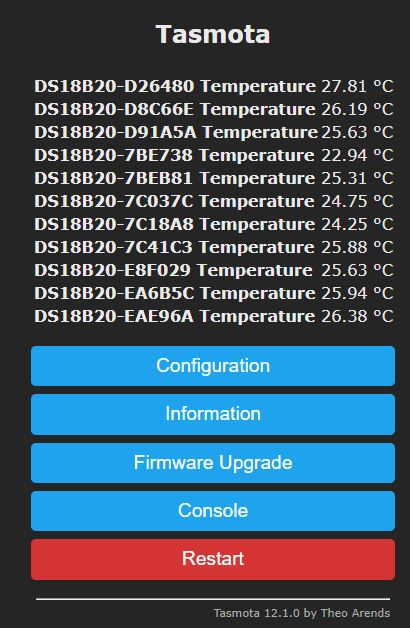
This project allows you to build a wide DS18B20 sensors network over a house
It uses :
- a D1 Mini (ESP8266)
- some DS18B20 sensors
- a customized Tasmota firmware
In order to get a wide 1-Wire bus (one that cover a house), Dallas provides some recommendations into their application note AN148.
This project use the Improved Interface bellow that is able to support a 200 meters long bus:
This one requires a pin for reading the bus state and another one as output to drive the bus low : I named it the "Dual Pin OneWire"
Warning : If you build a large 1 Wire bus inside your house, keep in mind that some voltage may appear on this one by induction. You need to have a good knowledge about electricity and associated risks!!!
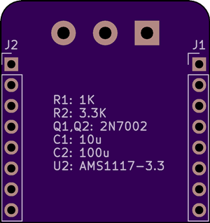
All files are inside schematic subfolder and has been designed with KiCad
Box project (Fusion 360) and STL files can be found into box folder
A specific variation in the Tasmota code needs to be done before compilation.
Compile it yourself by following bellow steps OR precompiled binaries are available in Releases.
You need to follow Tasmota guides to be ready for compilation:
https://tasmota.github.io/docs/Compile-your-build/
You need to edit tasmota/tasmota_xsns_sensor/xsns_05_ds18x20.ino file
- enable
#define DS18x20_USE_ID_AS_NAMEby removing the '//' - replace
#define DS18X20_MAX_SENSORS 8by#define DS18X20_MAX_SENSORS 16 - For PCB 3.0 and lower
- replace all
digitalWrite(DS18X20Data.pin_out, HIGH);bydigitalWrite(DS18X20Data.pin_out, newLOW); - replace all
digitalWrite(DS18X20Data.pin_out, LOW);bydigitalWrite(DS18X20Data.pin_out, HIGH); - replace all
digitalWrite(DS18X20Data.pin_out, newLOW);bydigitalWrite(DS18X20Data.pin_out, LOW);
- replace all
- save
- Compile Tasmota
- Rename resulting tasmota.bin to tasmota-WDS18B20-12.1.0.bin
You will find all available tools to flash tasmota in the official documentation:
https://tasmota.github.io/docs/Getting-Started/#needed-software
You need to apply this Template:
{"NAME":"WDS18B20","GPIO":[0,0,0,0,0,0,0,0,1344,0,1312,0,0,0],"FLAG":0,"BASE":18,"CMND":"Module 0|TelePeriod 60"}
To change number of digit after the dot on reported temperatures:
TempRes 2
To Enable arithmetic mean over teleperiod:
SetOption126 1
For more details, please refer to the Tasmota documentation:
https://tasmota.github.io/docs/DS18x20


