-
Notifications
You must be signed in to change notification settings - Fork 0
ESP32 setup
Martin Milchevski edited this page Nov 5, 2021
·
1 revision
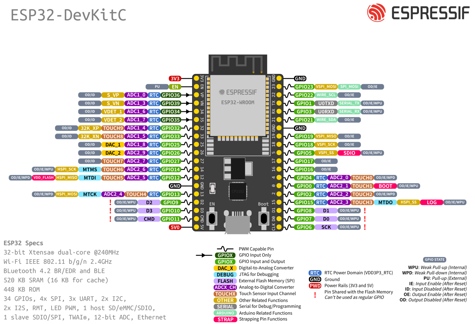
| USAGE | SERIAL | PINS ON ESP32 | ||
|---|---|---|---|---|
| Sensor 1 | > | a. | > | 36 |
| Sensor 2 | > | b. | > | 39 |
| Sensor 3 | > | c. | > | 34 |
| Sensor 4 | > | d. | > | 35 |
| Sensor 5 | > | e. | > | 32 |
| Sensor 6 | > | f. | > | 33 |
| Sensor 7 | > | g. | > | 25 |
| Sensor 8 | > | h. | > | 26 |
| Sensor 9 | > | i. | > | 27 |
| Battery | > | j. | > | 14 |


| 1 | 2 | 3 | 4 | ||||
|---|---|---|---|---|---|---|---|
| 1 | 256 | 257 | 512 | 513 | 768 | 769 | 1024 |
1.257.513.769
256.512.768.1024
| 0 | green |
|---|---|
| 1 | red |
| 2 | yellow |
| GPIO | Input | Output | Notes |
| 0 | pulled up | OK | outputs PWM signal at boot |
| 1 | TX pin | OK | debug output at boot |
| 2 | OK | OK | connected to on-board LED |
| 3 | OK | RX pin | HIGH at boot |
| 4 | OK | OK | |
| 5 | OK | OK | outputs PWM signal at boot |
| 6 | x | x | connected to the integrated SPI flash |
| 7 | x | x | connected to the integrated SPI flash |
| 8 | x | x | connected to the integrated SPI flash |
| 9 | x | x | connected to the integrated SPI flash |
| 10 | x | x | connected to the integrated SPI flash |
| 11 | x | x | connected to the integrated SPI flash |
| 12 | OK | OK | boot fail if pulled high |
| 13 | OK | OK | |
| 14 | OK | OK | outputs PWM signal at boot |
| 15 | OK | OK | outputs PWM signal at boot |
| 16 | OK | OK | |
| 17 | OK | OK | |
| 18 | OK | OK | |
| 19 | OK | OK | |
| 21 | OK | OK | |
| 22 | OK | OK | |
| 23 | OK | OK | |
| 25 | OK | OK | |
| 26 | OK | OK | |
| 27 | OK | OK | |
| 32 | OK | OK | |
| 33 | OK | OK | |
| 34 | OK | input only | |
| 35 | OK | input only | |
| 36 | OK | input only | |
| 39 | OK | input only |
