Using LPCScrypt to upload firmware to Smoothie2 via high speed USB
Using LPC21ISP to upload firmware to Smoothie2 via UART0
Using J-Link hardware dongle to program and debug Smoothie2
Debugging Smoothie2 with the MRI debug monitor
You can install LPCScrypt from here. Once you have it installed you should read the LPCScrypt_User_Guide. In particular, sections 3.2 and 3.3 which discuss additional steps that will probably be required on Linux and Windows. On OS X, the installer does everything that is required.
Here is a brief summary of what is required for Ubuntu platforms:
- LPCScrypt installs 32-bit binaries so 64-bit Ubuntu installs will need additional 32-bit library support:
- Ubuntu 13.04 of earlier: sudo apt-get install linux32 ia32-libs
- Ubuntu 13.10 and later: sudo apt-get install libc6:i386 libusb-dev:i386 uuid-dev:i386 libgtk2.0-0:i386 gtk2-engines-murrine:i386
- It can be nice to have the USB based serial ports exposed by the LPCScrypt second stage boot loader accessible from user mode:
- sudo scripts/install_udev_rules
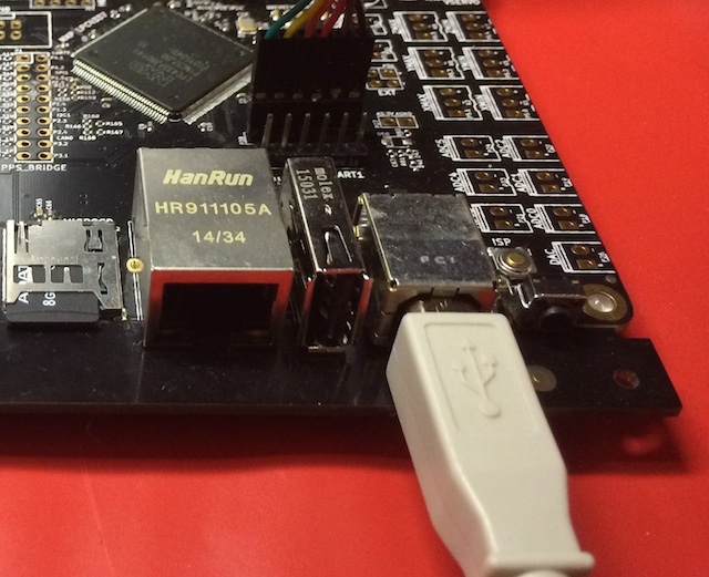
You will first want to connect a USB cable to the USB0 port on the Smoothie2 board. The following image shows a white USB cable being connected to the USB0 port, just left of the reset button.
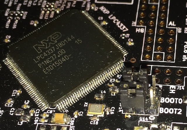
When my Smoothie2 board first arrived, it was configured to enter the slower UART0 boot loader when the ISP button is depressed during reset. It can be reconfigured to use the faster USB0 boot loader instead by moving the BOOT0 and BOOT2 jumpers to the high state (they both initially ship in the low state). The following image shows what these jumpers look like once they have been configured to use the USB0 boot loader.
To enter USB0 boot loader mode we now just need to:
- Press and hold down the ISP button.
- Press and release the RESET button.
- Release the ISP button.
Here are the commands that I used to program my Smoothie2 board on my MacBook.
/Applications/lpcscrypt_1.6.0_652/scripts/boot_lpcscrypt
/Applications/lpcscrypt_1.6.0_652/bin/lpcscrypt program +c LPC4330_M4/Smoothie2.bin BankA
/Applications/lpcscrypt_1.6.0_652/bin/lpcscrypt resetCore
A sample run from my machine:
/depots/Smoothie2/src$ /Applications/lpcscrypt_1.6.0_652/scripts/boot_lpcscrypt
Looking for DFU devices with VID 1fc9 PID 000c ...
dfu-util -d 0x1fc9:0x000c -c 0 -i 0 -t 2048 -R -D /Applications/lpcscrypt_1.6.0_652/scripts/../bin/LPCScrypt_103.bin.hdr
Booted LPCScrypt target (0x1fc9:0x000c) with /Applications/lpcscrypt_1.6.0_652/scripts/../bin/LPCScrypt_103.bin.hdr
/depots/Smoothie2/src$ /Applications/lpcscrypt_1.6.0_652/bin/lpcscrypt program +c LPC4330_M4/Smoothie2.bin BankA
....
Programmed 130072 bytes to 0x1a000000 in 1.210s (104.946KB/sec)
/depots/Smoothie2/src$ /Applications/lpcscrypt_1.6.0_652/bin/lpcscrypt resetCore
You may want to add the LPCScrypt bin/ and scripts/ directory to your path so that you don't need to use absolute paths like I did in my above sample run.
The lpc21isp application communicates with the LPC4337 via its UART0 peripheral. I used a FTDI USB to Serial cable from Adafruit to connect my MacBook Air to the device's UART0. I also powered the Smoothie2 board with the 5V VCC pin on this adapter. The data sheet found here documents the meaning of each of the colored pins on this FTDI cable. The diagram below shows how to attach the FTDI cable to the Smoothie2 board's UART0 header correctly.
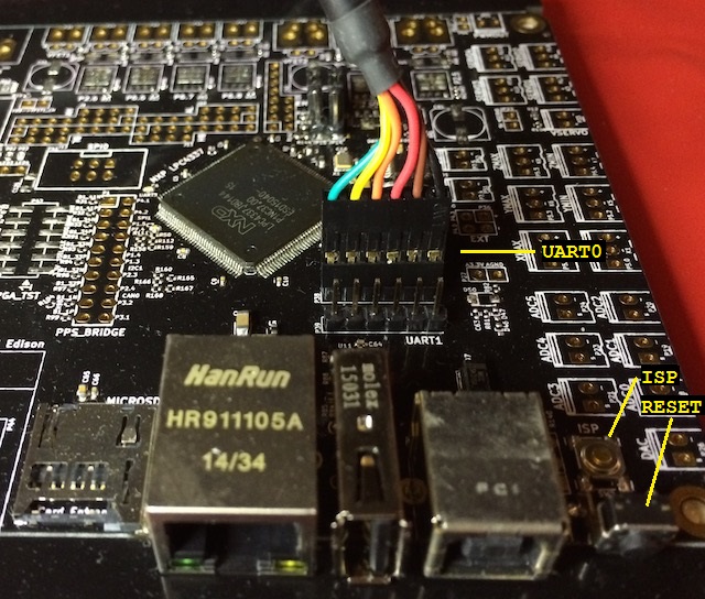
By default the Smoothie2 board is configured so that the LPC4337 response is to start running the code which has previously been loaded into the internal FLASH of the device. I needed to use a special reset sequence to get the LPC4337 to run the built-in ISP boot loader instead. In the photo above I point out the RESET and ISP buttons in the lower right portion of the image. To enter ISP mode we just need to:
- Press and hold down the ISP button.
- Press and release the RESET button.
- Release the ISP button.
Once the device is running the ISP boot loader, lpc21isp can be used to load new firmware into the internal FLASH of the device. I had an older version of lpc21isp on my machine but I had to pull down the latest sources from SourceForge and build a new version for my MacBook before I could get the utility to successfully connect to the LPC4337 device. Hopefully your favorite package manager will install a recent enough version of the utility to work with this device. If not, you will need to download the sources and build them for yourself as well.
I used the following shell commands to build the Smoothie2 sources and upload them to the Smoothie board.
cd src/
make
lpc21isp  LPC4330_M4/Smoothie2.hex /dev/tty.usbserial-FTDXR25Z 115200 12000
A few notes about the above:
- You will need to change /dev/tty.usbserial-FTDXR25Z to match the device name for the FTDI USB device on your machine.
- The baud rate of 115200 appears to be the highest rate that can be used by the LPC4337 when it is running in ISP mode where it uses the internal 12MHz IRC clock source.
The first step to working with the J-Link debugger is to install the necessary software from SEGGER.
- Go to https://www.segger.com/jlink-software.html
- Install the Software & documentation pack software appropriate for your operating system
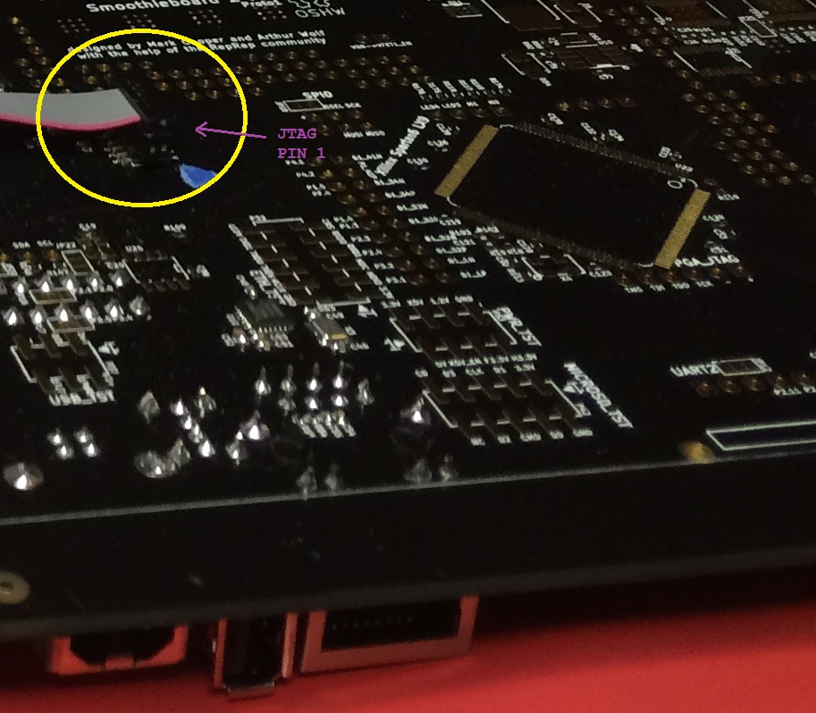
The J-Link debugger pod ships with a 20-pin JTAG cable. This cable is too large for the JTAG connector on the Smoothie2 board. A converter, like the JTAG (2x10 2.54mm) to SWD (2x5 1.27mm) Cable Adapter Board, is required. The 20-pin cable provided with the J-Link hardware is connected to the J-Link debugger pod on one end and then to the larger 2x10 header on the adapter board. The 10-pin 2x5 Socket-Socket 1.27mm IDC (SWD) Cable is connected to the smaller 2x5 header on this adapter board on one end and the JTAG header of the Smoothie2 board on the other. The 2x5 JTAG header for the LPC4337 microcontroller can be found on the bottom of the Smoothie2 board. I have highlighted pin 1 in the following photo. The red wire on the 10-wire JTAG debugger cable indicates which end of the cable socket should be connected to this pin 1.
Two programs are involved in using GDB to debug via the J-Link hardware debugger. One is a TCP/IP based debug server provided by SEGGER in the Software & documentation pack and the other is arm-none-eabi-gdb. They are each started as below:
- JLinkGDBServer -device LPC4337_M4 -endian little -if JTAG -speed 10000 -localhostonly
- arm-none-eabi-gdb -ex "set target-charset ASCII" -ex "set print pretty on" -ex "target remote :2331" -ex "set mem inaccessible-by-default off" LPC4330_M4/Smoothie2.elf
JLinkGDBServer connects to the J-Link hardware pod via the provided USB cable. The command line options it is given let it know that we are debugging a LPC4337 device (specifically the M4 core), the device is setup as little endian, using JTAG as the debug protocol instead of SWD, the JTAG protocol should run at 10MHz, and only allow GDB processes from the same machine to connect (reduces the security risk of remote connections to the debug stub).
arm-none-eabi-gdb connects to JLinkGDBServer via a TCP/IP socket on port 2331. It can then be used in a fashion similar to how MRI has been used to debug Smoothie firmware in the past.
It is possible to use GDB and the JLinkGDBServer to upload code into the LPC4337 via JTAG. I see upload speeds of >1MiB/sec when using this method.
From within GDB, you can issue the following commands to upload the binary contents of the specified .elf file into the microcontroller and start it executing again from a clean reset.
- CTRL+C
- load
- monitor reset
- continue
It is possible to link the MRI (Monitor for Remote Inspection) debug monitor into the Smoothie firmware and then use a secondary serial connection to debug Smoothie with GDB (GNU Debugger) if you don't have JTAG debug hardware.
The Smoothie makefile must be modified to enable MRI and have it linked into the firmware.
--- a/src/makefile
+++ b/src/makefile
@@ -5,7 +5,7 @@
 BOARD ?= Smoothie2Proto1

 # Set MRI_ENABLE to a value of 1 to enable the MRI debug monitor on the secondary UART.
-MRI_ENABLE ?= 0
+MRI_ENABLE ?= 1

 # Set MRI_BREAK_ON_INIT to a value of 0 if you don't want MRI to break before running global constructors.
 MRI_BREAK_ON_INIT ?= 1
When switching between builds which enable and disable MRI, you should issue a make clean.
You will need to connect a USB to serial adapter to the UART0 port on your Smoothie2 board to allow GDB to connect to MRI running on the LPC4337. I use a FTDI USB to Serial cable from Adafruit to make this connection. The diagram below shows how to attach the FTDI cable to the Smoothie2 board's UART0 header correctly.
GDB should have been installed along with the GCC compiler and other GNU tools used to build the Smoothie2 source code.
From a Terminal or Command Prompt that is able to build Smoothie2, you should set the current directory to the src/ directory of the Smoothie project and use one of the following commands to launch GDB. The main difference between the operating systems is the type of name used for the serial port. You will need to substitute the serial device designator appropriate for your setup.
Windows:
arm-none-eabi-gdb LPC4330_M4\Smoothie2.elf --baud 230400 -ex "set target-charset ASCII" -ex "set remotelogfile mri.log" -ex "set mem-inaccessible-by-default off" -ex "target remote com1"
OS X and Linux:
arm-none-eabi-gdb LPC4330_M4/Smoothie2.elf --baud 230400 -ex "set target-charset ASCII" -ex "set remotelogfile mri.log" -ex "set mem-inaccessible-by-default off" -ex "target remote /dev/tty.usbserial-FTDXR25Z"