I. Hardware Explaination
![]()
The Transmitter Node uses an Arduino Uno to support 4 sensors, 2 actuators and a transmitter.
###Sensors
All Four of these sensors are used to collect metrics from the cactus that is currently supported by AgriTRAK.
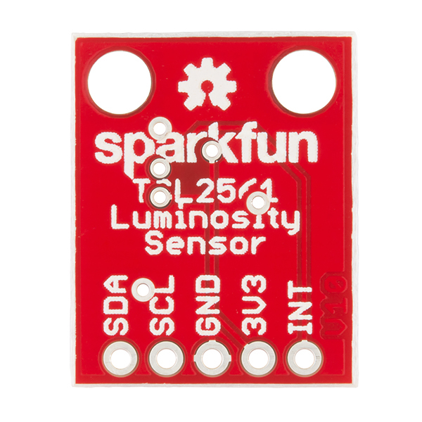
####SENSOR 1: LUMINOSITY SENSOR
Sensor Name: Sparkfun Luminosity Breakout Sensor
Sensor ID: TSL2561
Sensor Info:
The Luminosity Sensor uses I2C communication to interface with the Arduino Uno. The data collected from this sensor is used to control the lighting system, and it is transmitted to the receiver node.
####Sensor 2: UV Light Sensor
Sensor Name: UV Sensor Breakout
Sensor ID: ML8511
This sensor uses a library method to calculate the ambient ultraviolet intensity. AgriTRAK also has included a method that ensures that the sensor output is converted into the proper units.
Sensor Info:

####Sensor 3: Water Temperature Sensor
Sensor Name: Sparkfun - Temperature Sensor - Waterproof
Sensor ID: DS18B20
The water temperature sensor uses the oneWire library to interface with the Arduino Uno. The temperature data is transmitted to the receiver node.
Sensor Info:

####Sensor 4: Soil Moisture Sensor
Sensor Name: Sparkfun Soil Moisture Sensor
The soil moisture sensor acts as a variable resistor. As the soil moisture increases, the resistance of the sensor decreases. This causes the voltage to increase as soil moisture increases. The data from this sensor is used to control the irrigation system, and it is also transmitted to the receiver node.
Sensor ID: SEN - 13322
Sensor Info:

###Actuators
####Actuator 1: Pump
Actuator Name: 6V Paristaltic Pump

####Actuator 2: Light
Actuator Name: 3 Band LED groLight

###Transmitter
Transmitter Name: Sparkfun RF Link Transmitter
![]()

The receiver node is comprised of three main components: the Arduino Uno, the WRL-10532 RF Link Receiver, and the Adafruit HUZZAH ESP8266 wifi microcontroller.
The RF Receiver has one transmission pin on both sets of four pins. We used only the left side of the receiver for our purposes. The leftmost pin goes to ground, the second leftmost pin goes to digital pin 11 of the Arduino (green wire), and the rightmost pin goes to V+. On the right side of the receiver, the rightmost pin goes to V+ and the two middle pins go to ground.
The ESP8266 wifi microcontroller is programmed independently of the Arduino Uno using a console cable, as shown below.
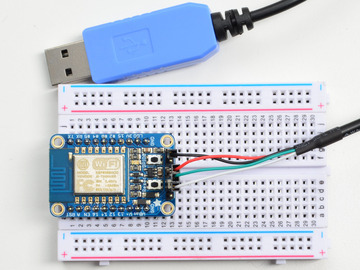
The console cable is wired as follows: black wire to ground, red wire to V+, white wire to TX, and green wire to RX.
The ESP8266 communicates with the Uno via serial communication. As a result, the RX pin (receive data) of the ESP8266 is connected to the TX pin (transmit data) of the Uno (purple wire). Note: the ESP8266 must also share common ground with the Uno in order to properly serially transmit data.

For more information, see: https://www.adafruit.com/product/2471