A compilation of lab activities in our logic circuits class.
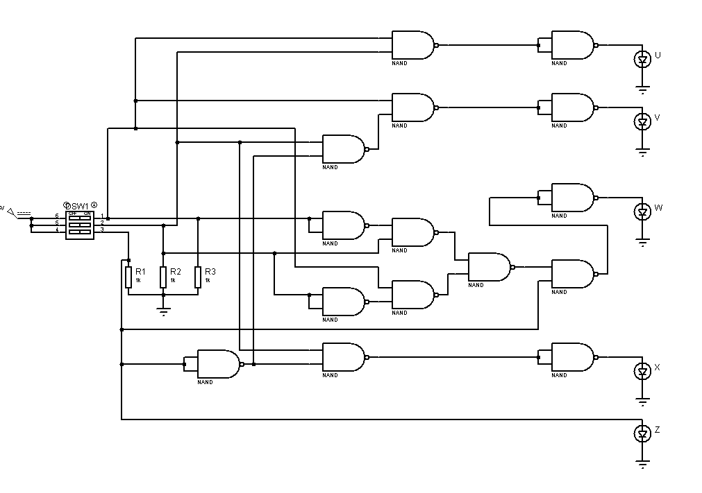
A decoder is a combinational logic circuit that changes a code into a set of signals. Generally a decoders output code normally has more bits than its input code. The circuit designed here is able to output the square equivalent of the input in 6-bit number, provided that only a 3-bit number (0-7) is inputted.
Design a combinational logic circuit that accepts a 3-bit number and generate a 6-bit binary number output equal to the square of the input number.
- Basic Gates
- NAND Gates
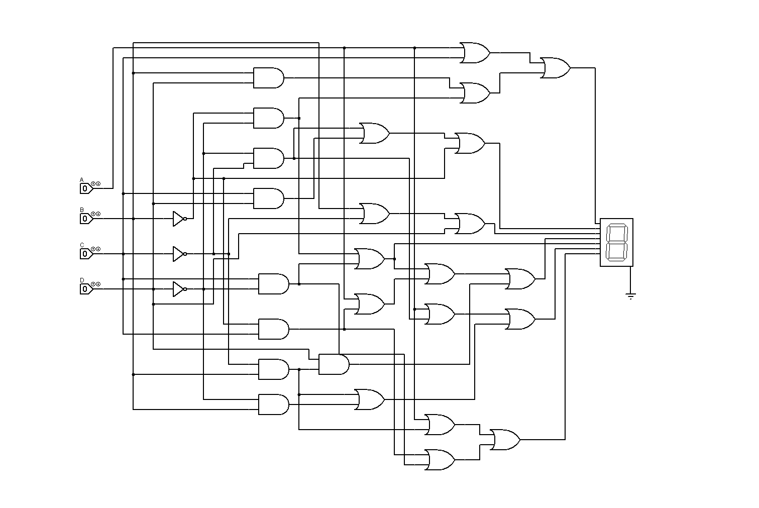
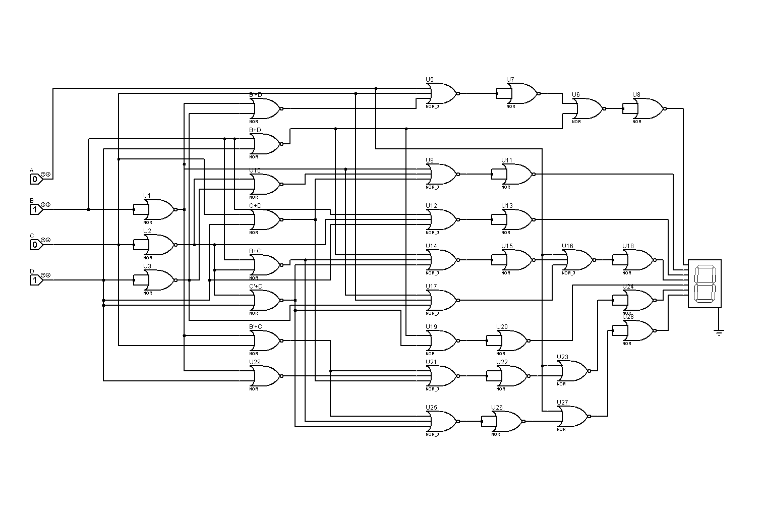
A BCD to Seven-segment is a combinational circuit that accepts a decimal point in BCD and generates the appropriate outputs for selection of segments in a display indicator used for displaying the decimal digit.
Design the BCD to seven-segment decoder utilizing the least number of logic gates.
- Basic Gates
- NOR Gates
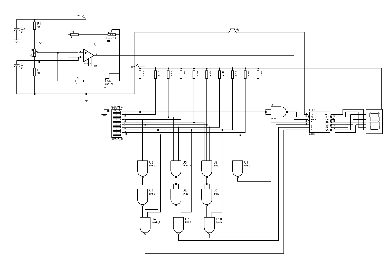
Encoders are used to translate the decimal values to the binary in order to perform the binary functions such as addition, subtraction, multiplication, etc. It is the reverse of a Decoder in its function.
Design an encoder circuit that accepts 0-9 decimal switches and can display the equivalent results in a seven segment display.
- All segments are OFF if all switches are OFF.
- Provide a switch for lamp test.
- The brightness of the segments can be tested.
- Common cathode & a logic low input
- Common anode & a logic high input
Design a simple Arithmetic Logic Unit with one selector variable S and two input A and B. When S=0, the circuit performs A+B. When S=1, the circuit performs A-B by taking the two’s complement of B. Assume that A and B to be decimal digit. Use any available package decoder as output converter into a seven segment display. Unsigned bits only. For this activity, a BCD adder will be used.


