Configuration
Ground and flight controllers configurations are managed by a LuaJIT instance, allowing a great flexibility of use.
Notes :
- On Raspberry Pi pin numbers are their BCM identifier, refer to https://pinout.xyz/ (
2means GPIO 2 on pin header 3).
The flight controller is not garanteed to fly if any of these are not set up.
The frame variable holds the motors configuration and some specific settings related to the type of UAV.
It must be one of the following classes :
-
Multicopter
Can handle any amount of motors by using the appropriate matrix
Available settings :-
motors
list of connected motors -
matrix
list ofVectordefining how each motor is affected by roll/pitch/yaw/thrust values -
air_mode
Air-Mode specific settings-
triggerSets the throttle speed (between 0.00 and 1.00) at which air-mode is activated, this prevents erratic movements on take-off. Once active, it will stay on until the drone is disarmed. -
speedSets the minimum motors speed (between 0.00 and 1.00) when air-mode is active, this prevents the motors to not being able to restart because of friction while in mid-air. Should be set to the lowest possible value that keeps the motors running smoothly.
-
-
The motors array should be a list of one or several of the following classes (they do not have to be the same, several motor types can be used on the same frame) :
-
BrushlessPWM( pin_number, min_µs, max_µs )
min_µs defaults to 1060, max_µs default to 1860 -
OneShot125( pin_number, min_µs, max_µs )
min_µs defaults to 125, max_µs default to 252 -
OneShot42( pin_number, min_µs, max_µs )
min_µs defaults to 42, max_µs default to 80 -
DShot( pin_number )(recommended)
frame = Multicopter {
	maxspeed = 1.0,
	air_mode = {
		trigger = 0.25,
		speed = 0.15
	},
	-- Set how many motors are used, and how each of them should be controled
	motors = {
		DShot( 4 ),
		DShot( 5 ),
		DShot( 6 ),
		DShot( 7 ),
	},
	-- Set multipliers for each motor ( input is : { Roll, Pitch, Yaw, Thrust }, output is how much it will affect the motor )
	matrix = {
		Vector( -1.0,  1.0, -1.0, 1.0 ), -- motor 0 = -1*roll + 1*pitch - 1*yaw + 1*thurst
		Vector(  1.0,  1.0,  1.0, 1.0 ), -- motor 1 =  1*roll + 1*pitch + 1*yaw + 1*thurst
		Vector( -1.0, -1.0,  1.0, 1.0 ), -- motor 2 = -1*roll - 1*pitch + 1*yaw + 1*thurst
		Vector(  1.0, -1.0, -1.0, 1.0 )  -- motor 3 =  1*roll - 1*pitch - 1*yaw + 1*thurst
	}
}The imu (Inertial measurement Unit) variable holds the sensors and their filtering configuration.
There is currently only one implementation :
-
IMU
Available settings :-
gyroscopesholds a list of gyroscopes that must be used by the IMU -
accelerometersholds a list of accelerometers that must be used by the IMU -
magnetometersholds a list of magnetometers that must be used by the IMU -
altimetersholds a list of altimeters that must be used by the IMU -
gpsesholds a list of GPS devices that must be used by the IMU
-
filters
Most of the filtering is handled by a simplified Kalman filter
-
ratesGyroscopes filtering -
accelerometerAccelerometers filtering -
attitudeSensor fusion between gyroscopes, accelerometers and magnometers to determine absolute angular position
-
-
-- Instanciate an ICM4xxxx sensors connected to SPI-0, ChipSelect-0 with 2MHz data rate
local imu_sensor = ICM4xxxx {
	bus = SPI( "/dev/spidev0.0", 2000000 )
}

imu = IMU {
	gyroscopes = { imu_sensor.gyroscope },
	accelerometers = { imu_sensor.accelerometer },
	magnetometers = {},
	altimeters = {},
	gpses = {},
	-- Setup Kalman filters
	-- 'input' represents the amount of smoothing ( higher values mean better stability, but slower reactions, between interval ]0.0;+inf[ )
	-- 'output' represents the quantity of the filtered results that is integrated over time ( between interval ]0.0;1.0[ )
	filters = {
		-- gyroscopes filtering
		rates = {
			input = Vector( 80, 80, 80 ),
			output = Vector( 0.25, 0.25, 0.25 ),
		},
		-- accelerometers filtering
		accelerometer = {
			input = Vector( 350, 350, 350 ),
			output = Vector( 0.1, 0.1, 0.1 ),
		},
		-- attitude filtering (gyroscopes + accelerometers fusion)
		attitude = {
			input = {
				accelerometer = Vector( 85, 85, 100 ),
				rates = Vector( 12, 12, 12 ),
			},
			output = Vector( 0.45, 0.45, 0.45 ),
		},
	}
}The controller variable is used to set how controls and telemetry communication is handled. There is currently one implementation :
-
Controller-
expohelps pilot to control the drone more smoothly by reducing roll-pitch-yaw control values on small movements, and increase throttle value on lower part (as drone needs at least 15~20% to lift-off, these first 20% steps are useless). The final values are passed to thestabilizer -
linkholds an instance of theLinkclass that is used to communicate with ground
Supported links (see also Links) :-
SBUS(with limited functionalities) -
SX127x(FSK / LoRa) -
Socket(TCP / UDP / UDP-Lite) -
RawWifi
-
-
telemetry_ratesets how many times per second telemetry data is sent to ground, can be 0 to disable -
full_telemetrysets if full telemetry must be sent ()
-
controller = Controller {
expo = Vector(
4, -- ROLL : ( exp( joystick_input * expo_roll ) - 1 ) / ( exp( expo_roll ) - 1 ) => must be greater than 0
4, -- PITCH : ( exp( joystick_input * expo_pitch ) - 1 ) / ( exp( expo_pitch ) - 1 ) => must be greater than 0
3.5, -- YAW : ( exp( joystick_input * expo_yaw ) - 1 ) / ( exp( expo_yaw ) - 1 ) => must be greater than 0
2.25 -- THURST : log( input * ( thrust - 1 ) + 1 ) / log( thrust ) => must be greater than 1
),
link = Socket {
type = Socket.UDP,
port = 2020,
read_timeout = 500
},
telemetry_rate = 20,
full_telemetry = false
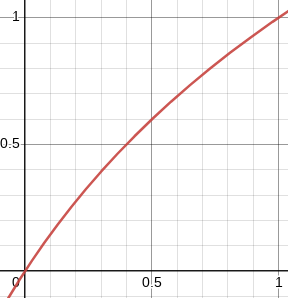
}Expo value for roll and pitch with 4 :

Expo value for thrust with 2.25 :
There is only one stabilizer implementation for now, it's responsible of producing corrected attitude/position based on current measured attitude from imu and desired user controls from controler. Generated values are passed to frame, which apply these to the motors according to its configuration matrix.
-
Stabilizer-
loop_timeTime, in micro-seconds, at which the stabilizer updates its data (reading IMU + producing new attitude / position) -
rate_speedMaximum angular speed of the drone, higher values will make drone more reactive but more uncontrollable -
pid_rollPID( P, I, D ) settings for the Roll axis -
pid_pitchPID( P, I, D ) settings for the Pitch axis -
pid_yawPID( P, I, D ) settings for the Yaw axis -
horizon_anglesMax tilt angle when flying in horizon stabilized mode -
pid_horizonPID( P, I, D ) settings for the horizon stabilized mode, this affect both Roll and Pitch axes
-
The PID datatype allows to set global P, I and D scales that are applied to any PID(...) declarations.
-- same scales as betaflight
PID.pscale = 0.032029
PID.iscale = 0.244381
PID.dscale = 0.000529
--- Setup stabilizer
stabilizer = Stabilizer {
	loop_time = 500, -- 500 µs => 2000Hz stabilizer update
	rate_speed = 1000, -- deg/sec
	pid_roll = PID( 45, 70, 40 ),
	pid_pitch = PID( 46, 70, 40 ),
	pid_yaw = PID( 45, 90, 2 ),
	horizon_angles = Vector( 20.0, 20.0 ),
	pid_horizon = PID( 150, 0, 0 )
}