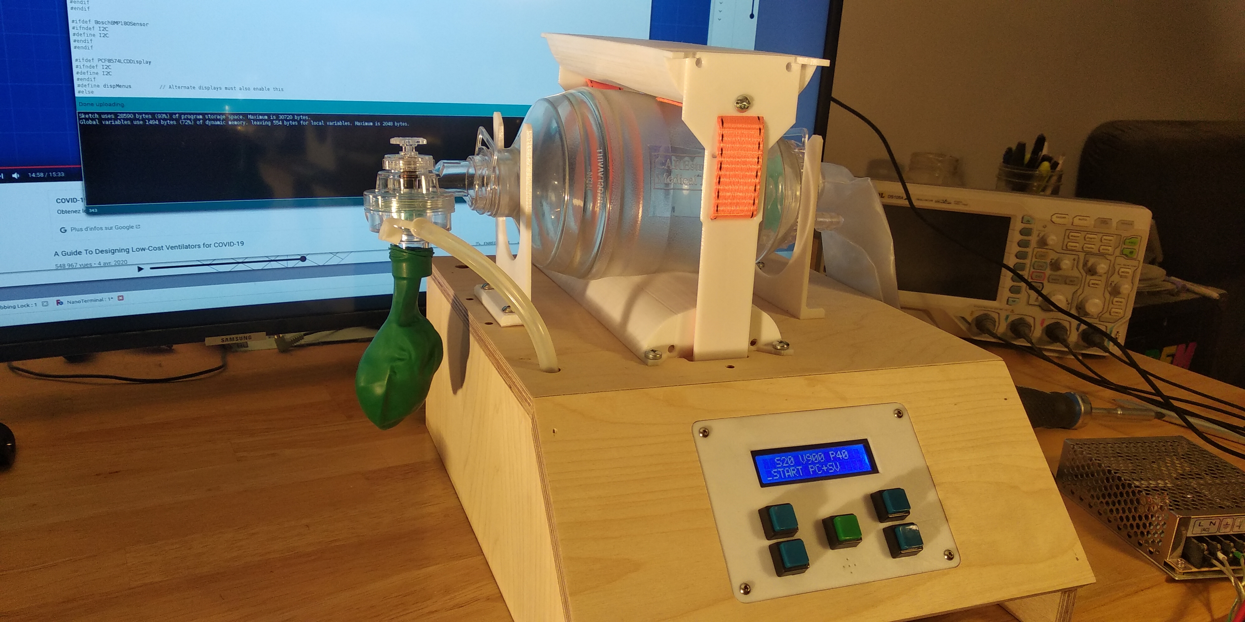
The project now contains a complete functional ventilator (prototype stage) with both the controller, and the complete mechanical design, all the 3D printed parts (both STL & CAD files) as well as the CNC files for the box.
The complete part list will be updated soon.
Video presentation / demo :
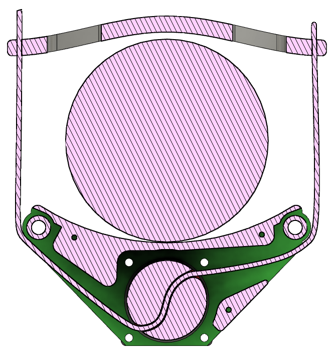
The mechanism uses a simple but effective drive mechanism based on a single high strength nylon or polyester webbing strap to squeeze the bag from both sides with minimal mechanical losses. This design (author unknown) inspired me to explore this solution.
A major change was to use a much smaller diameter aluminum shaft instead of a drum as this gives the required torque. Also lateral guides are added to ensure a better stability. Also the parts in contact with the BVM are convex instead of being concave as the shape squeezes the BVM in a way that allows to extract more air with minimal force and without damaging the BVM.
The motor is also more powerful than in many other designs I've seen while retaining good position control, allowing it to compress the BVM fast, precisely even at high pressure.
The previously released control software is compatible with this mechanical design and many others.
This software is designed to control a Bag Valve Mask (BVM) AmbuBag medical Ventilator as part of the global effort to develop a fast, effective, easily replicable device using distributed digital manufacturing techniques including 3D printing, CNC or laser cutting. The project uses an Arduino Nano with Atmega328P. The software can be used with a wide range of mechanical designs.
Short video presentation / demo :
(I'm not a youtuber and English's not my main language, you've been warned !)
NOTE: Requirements for a minimal emergency ventilator device have been issued by the UK government, and now the WHO as part of a Disease commodity package. This controller strives to follow these guidelines.
Thanks to uxvrob we now have a complete schematic diagram so that the controller can be tested.
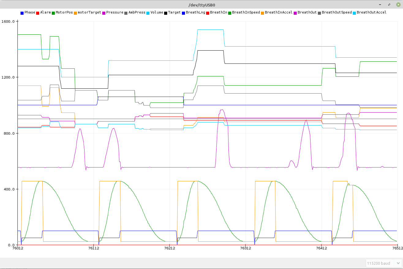
As of V0.20, the controller now outputs data that can use an external HMI or the Arduino plotter to output realtime data. Actual plot below (the pink pressure trace was generated by manually pressing an ambu-bag. The right of the screen shows a pressure limited cycle).
(release notes are at the end)
-
The arduino Nano was chosen as a controller for it's ability to perform the realtime tasks with relatively low latency (step generation & data acquisition) and it's universal availability. More sophisticated controllers such as the Raspberry Pi usually have real time issues and unpredictable latency. Also, the Arduino ecosystem is very rich in well tested libraries.
-
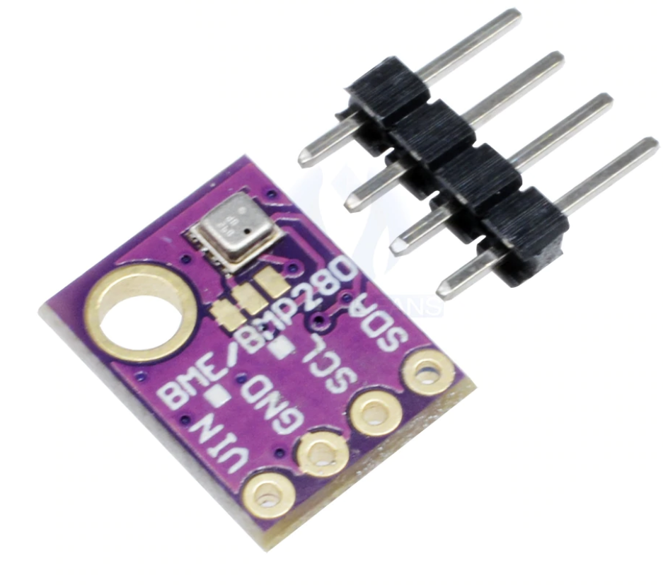
The Bosch Sensortech BME280 / BMP280 sensor allows precise measurement of the air pressure delivered to the patient. It also allows measurement of the temperature and pressure (BME280 only). The software allows to use either of these. It'a a well known, mass produced, low cost sensor. https://www.bosch-sensortec.com/products/environmental-sensors/humidity-sensors-bme280/
-
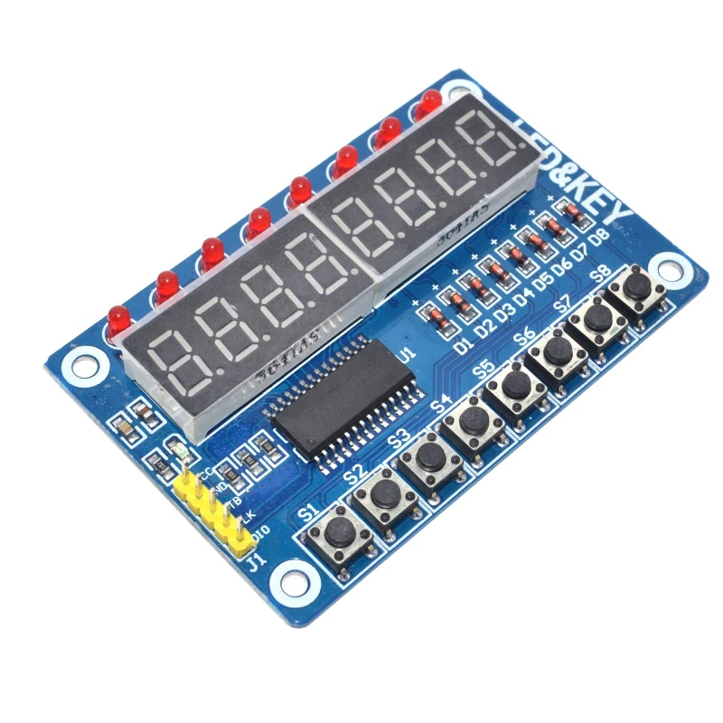
The TM1638 display / LED / keyboard This little board merges leds, a 8 digits 7 segments display and 8 buttons. It's a very common Chinese board that possesses numerous advantages. It's main drawback is the Old School look of it's display, but does it really matter for this usage ? The main advantages are that the board is mechanically integrated making mechanical assembly very easy. Connection to the processor uses only 3 pins (Data, Clock, Strobe) The data is clocked and not timing sensitive. The whole board typically costs 1.50$ 2x16 character LCDs require a lot of pin connections or, when used with a "backpack", they require a serial interface. Also, the LCD needs a temperature dependant analog adjustment to be well readable. The display is not very bright and can't be read from a distance. That could be a problem when a person has to monitor several heavily infected patients. They also require a separate keyboard. OLED displays are not suited for this device as their active lifetime is limited. color LCDs would be another possibility, possibly with a touchscreen, but it would take longer to develop and require a more powerful processor without adding much to the main function of the device.
-
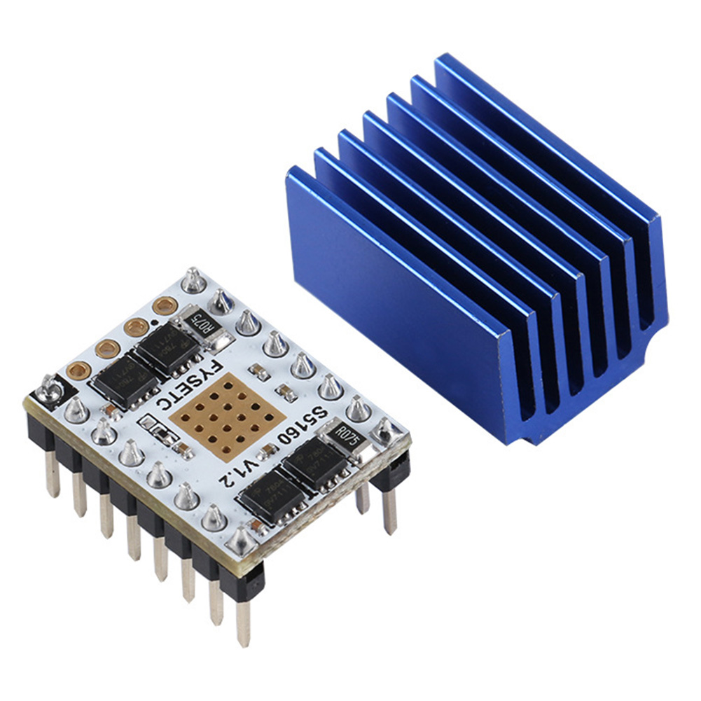
StepStick stepper driver The stepstick stepper motor drivers are widely available as they are used to drive 3D printer motors. When used with 24V and a low current/high torque NEMA23 motor, they can offer a very good torque. There are several types depending on the chip they use (A4988 / DRV8825 / Trinamic TMC2209 & TMC5160). The TMC5160 drives up to 4.4Amps and is even suitable for a NEMA24 or NEMA34 motor. All Trinamic drivers include advanced functions such as load measurement, stall prevention and detection, noiseless operation, etc ... https://www.trinamic.com/products/integrated-circuits/ Since the software uses industry standard STEP/DIR interface, any external driver may be used to control a stepper, a servo-stepper or a 3 phases servo. A servo would probably be required for a leadscrew design, while a stepper would be more suited to a direct drive design.
To compile the software, you will need the following libraries (all from the library manager) :
#include <BME280I2C.h>             // Temperature / humidity / pressure
                                   //  by Tyler Glenn - https://github.com/finitespace/BME280
#include <Wire.h>                  // I2C protocol
#include <EEPROM.h>                // read / write to the processor's internal EEPROM
#include <TM1638plus.h>            // Keyboard / display / LED combo board
                                   //  By Gavin Lyons - https://github.com/gavinlyonsrepo/TM1638plus
#include <AccelStepper.h>          // Stepper / servo library with step pulse / dir interface
                                   //  By Mike McCauley - http://www.airspayce.com/mikem/arduino/AccelStepper
#include "TimerOne.h"              // Timer component
                                   //  By Jesse Tane, Jérôme Despatis, Michael Polli, Dan Clemens, Paul Stroffregen
                                   //  https://playground.arduino.cc/Code/Timer1/
#include <LiquidCrystal_PCF8574.h> // LCD with PCF8574 "backpack"
                                   //  Matthias Hertel - http://www.mathertel.de/Arduino/LiquidCrystal_PCF8574.aspx
The software is contained in an Arduino "sketch" with many comments, nearly all parameters are in defined constants and can be easily changed. It is herein distributed under the GPL V3.0 licence. The software has the following functions:
-
Initialisation with display keyboard and sensor detection. The software have been designed to allow operation in degraded mode without BME/BMP280 sensor and even without keyboard / display (it will autostart with stored parameters) During the startup process, detailed debug information is provided through the serial/USB port. TBD : remote operation controlled by USB
-
User interface The software manages the display, keyboard navigation in the settings menu and an alarm beeper. The 8 leds above the keyboard are used as a bar-graph of the measured pressure and a breath cycle indicator. The 3rd LED represent neutral atmospheric pressure and blinks at the start of each breathing cycle. 1st and 2nd LEDs on the left indicate a low pressure, those on the right indicate a higher pressure. Display is scaled according to the preset pressure. The menu allows to change the following parameters:
-
Pulse rate The pulse rate in breathing cycles per second can be adjusted between 5 and 60 BPM.
-
Breathing volume The breathing volume in liter per cycle can be adjusted between 0.1l and 2l. The motor travel and acceleration are changed according to this parameter. There is a yet to be determined limit for high volume at high pulse rate depending on the mechanical design.
-
Breathing Pressure The breathing pressure in KPa can be adjusted between 3Kpa and 30Kpa. The pressure is used to limit the motor speed / travel to prevent exceeding the preset value. TBD : This feature is not fully implemented yet (but measurements are available and the stepper library allows to alter the motor parameters while it's rotating).
-
Save settings This saves the 3 settings above and the running state, thus allowing for automatic start upon powerup.
The user interface management is done in a timed interrupt to be responsive and remain functionnal at all times, so that all parameters can be visualised and changed while the device is operating.
When changing the settings, the change will be gradual with each subsequent breath cycle to prevent sudden changes. The variation speed can be defined for all parameters.
- data acquisition. Data is acquired from the BME/BMP280 sensor every 100ms. the acquisition includes filtering of the pressure
This browser does not support PDFs. Please download the PDF to view it: "Download Schematic
-
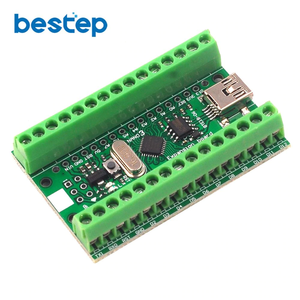
Arduino Nano Any arduino Nano or clone can be used, as long as it contains an Atmega328 processor https://www.aliexpress.com/item/32845440152.html
-
Bosch Sensortech BME280 / BMP280 sensor breakout Warning, there are 3.3V breakout and 5V breakout boards. Some have 4 pins, others 6 pins. They can all be used. Connect the supply accordingly, the 2 extra pins are unused (SPI) https://www.aliexpress.com/item/32672562548.html
-
TM1638 Display / Leds / Keyboard combo module They all have the pin header on top, you can remove the plastic part and bend the pin for side connection There are other types of boards with TM1638 chip with 16 buttons, but they lack the LEDs that are important to monitor air pressure measurement. https://www.aliexpress.com/item/32807348409.html
-
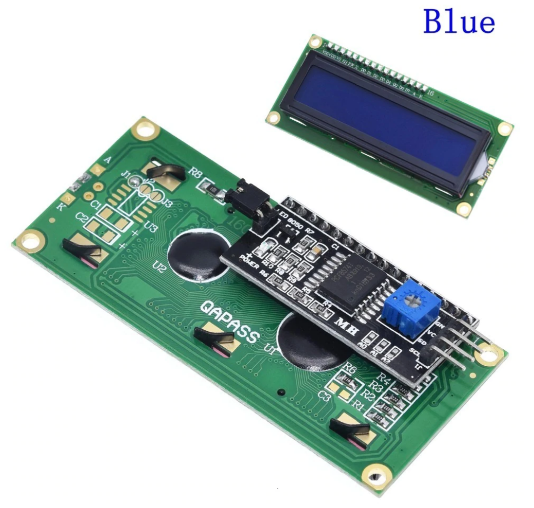
HD44780 With PCF8574 2 lines x 16 character LCD with I2C interface These are standard LCD display, and the I2C interface (PCF8574) allows them to be used without taking up many I/O pins. https://www.aliexpress.com/item/32651314933.html
-
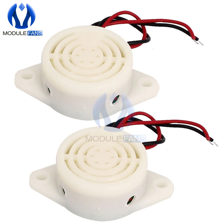
Beeper This active beeper is easy to drive and the sound level is mild. https://www.aliexpress.com/item/1893768547.html Here is a louder one. https://www.aliexpress.com/item/32671465979.html
-
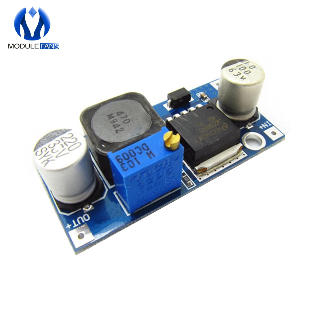
Regulator Even at 12V, the motor can generate spikes that will damage the controller's regulator. These regulators are cheap, and rated for high voltage (max 50V). The potentiometer needs to be adjusted for 7.5V to 8V https://www.aliexpress.com/item/1859113573.html
-
Driver and motor. The driver and motor required will depend on the mechanical design used. here are a few : Cheapest, but rugged A4988 Stepstick: https://www.aliexpress.com/item/1851964212.html DRV8825 StepStick https://www.aliexpress.com/item/1937880897.html TMC2209 StepStick (silent, with torque detection). Could approximate a pressure measurement for a setup without pressure sensor. https://www.aliexpress.com/item/33029587820.html TMC5160 StepStick (by far the best option, 4.4A/phase, can drive NEMA34 steppers) https://www.aliexpress.com/item/33051621409.html As latest calculations ans experimental setups indicate the need for a more powerful motor, a LeadShine DM542S (50V 5A seems necessary. https://www.aliexpress.com/item/32953743944.html
For direct drive, a large Nema23 motor with low current and high torque would be best. these motors quickly lose torque as their speed increases, but in this application, their performance should be a good match. This one is rated for 1.9NM with only 2.12A (bipolar mode) https://www.aliexpress.com/item/4000032106569.html
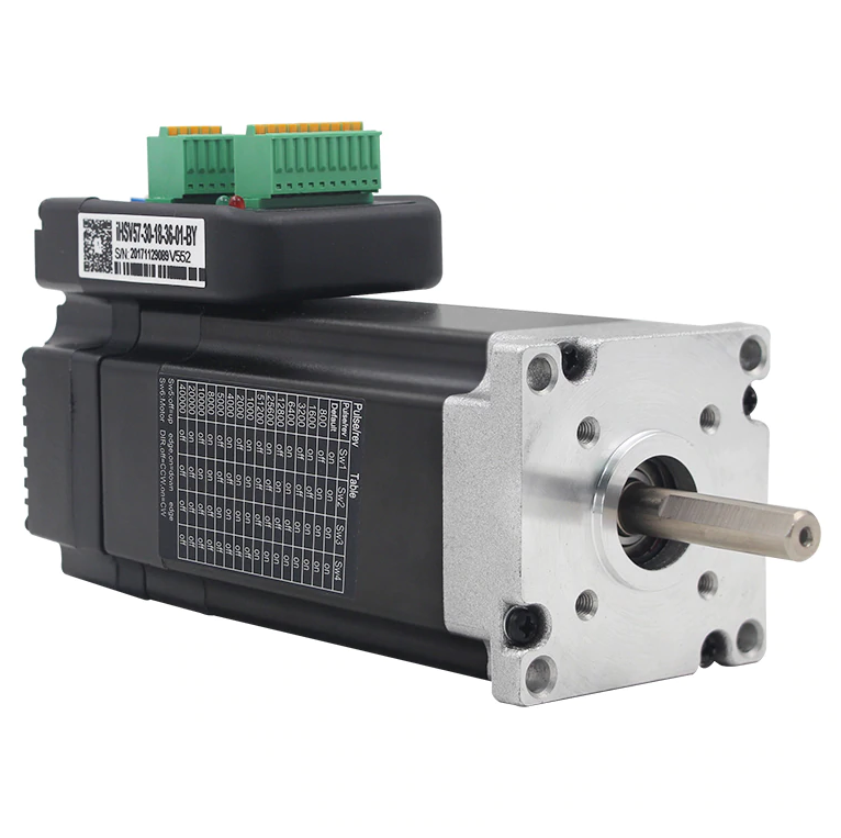
For designs using a ballscrew, a servomotor is required to get the necessary speed. Here is a good, not too expensive option with integrated controller: 180W 3000 RPM version https://www.aliexpress.com/item/4000333220649.html 100W 3000 RPM version https://www.aliexpress.com/item/32945533935.html
-
0.10 Initial public version
-
0.11 Add interactive terminal command line complete control (through USB link) A minimal device without screen or keyboard is possible with the same software.
-
0.12 Add "Assist Control" mode with adaptive negative pressure trigger cycle. This mode was requested by a MD :
"ER doc here chiming in, hopefully I can answers some questions or clarify minimal requirements.The basic mode you need is Assist Control. This mode provides a breath whenever the patient triggers a breath (by inhaling and creating negative pressure past a certain threshold) or whenever the patient is due for a breath (based on the set rate). The breath it provides are either a fixed volume (and the doc monitors the pressures delivered) or a fixed pressure (and the doc monitors the volume delivered). AC/volume is often called Volume Control, and AC/pressure is often called Pressure Control. While I do not have direct experience ventilating COVID patients yet, these 2 modes will cover 99% of ICU cases."This version also adds editing, permanent storage and USB setting of the new Patient Synchronization parameter and an audible alarm when pressure remains above 120% of preset pressure for 1 second or mode. -
V0.13 Modular code - asymmetric breathing - Bug fix This version is a major reorganization of the code done to get a more modular software, ready for bringing in other sensors, a different user interface and ports to other controller architectures. Very long functions are broken down into smaller functionnal blocks that should be much easier to understand and modify, each global variable is commented. This version also implements most of the guidelines in the UK minimal emergency ventilator device specifications. Namely, all variable limits have been tweaked and the variable Inspiratory:Expiratory ratio is fully functionnal. A bug that allowed floating point variables retrieved from a garbage filled EEPROM to bypass the checks leading to malfunction have been corrected (NaN detection).
-
0.14 This version include proper timing, speed and acceleration for the motor control. The pressure controlled and volume controlled modes are implemented.
-
0.15 Minor version change. This version allows the replacement of the buggy Wire.h arduino library (can hang the controller) with a correct version known as jm_Wire https://github.com/ermtl/Open-Source-Ventilator/blob/master/OpenSourceVentilator/README.md 'Wire.h' is still the default library to prevent compiler errors. The processor's hardware watchdog can now be enabled (off by default, use with care, you risk bricking your processor. Modularisation is getting better (work in progress)
-
0.16 Double pressure sensor, breath phases modularization This version can use 2 absolute sensors (or still use just 1, configurable) to constantly monitor the ambiant air pressure. This is important for patients that are heliported and for patients placed in a negative pressure room, 2 situations where the ambiant pressure can change rapidly. The 2 sensors together will behave as a differential pressure sensor. Since pressure is a critical data, several safeguards and coping strategies have been added to make sure data from the sensor is acurate and there is a failsafe. Things such as randomly connecting/disconnecting sensors are non blocking and behave as expected. this feature requires the #define jm_Wire to be uncommented.Please see the link in the description for version 0.15 above
Also, as requested, the various phases and functions managing the breathing cycle itself have been modularized to allow third parties to implement more sophisticated control strategies. Finally, the processor's program memory is filing up quickly as the control becomes more complex. There is still opportunities for important optimizations, but the base version will have to give up some non essential functions to fit in a regular Arduino Nano (such as the verbose serial interface or the ability to manage both the native keyboard / display and the USB serial command line interface. This version barely fits with the USB commands on, so they've been deactivated. You can get them back by uncommenting the #define USBcontrol line. The following versions will both target the Nano and the Mega with Atmega2560 processor for 8 times the available program memory. -
0.17 2x16 LCD Display - Telemetry
  The ability to use an alphanumeric 2 lines * 16 characters LCD display had been
  requested, it will now be fully supported. Since this LCD uses lots of IO pins,
  the retained version is connected to a PCF8574 "Backpack" board to make it I2C
  compatible. The LCD+the backpack are sold online for around 2.50$.
  The TM1638 display is still supported as a minimal option.
  A good side effect is that the library is lean and so USB/serial terminal control
  is back by default.
  At this point, the keyboard and bargraph are still done with the TM1638, but a
  simple button keyboard will be supported very soon.
  Telemetry will send information in real time about the breathing cycle for further
  data analysis and / or graphical display !
  This will be very very useful for people developing mechanical solutions, and
  doing data analysis to develop motor position <=> volume mapping
  Data is sent in common CSV format, around 1 data point every 20 millisecond
  The "T" command, sent through the serial port toggles telemetry on or off.

  every data point includes :
  - Time since the breathing was activated.
  - Breathing cycle phase (more phases might be added in the future)
    0 : Start of new cycle
    1 : Inspiration
    2 : Start of expiration
    3 : Expiration
    4 : Patient breathing initiation search
    5 : Patient initiated a breathing cycle
   - Motor position (in step) Travelled distance depends on driver microstepping
                              and driving mechanism.
   - relative pressure in cm H2O

  In addition to these data points, during phase 0 (start of cycle), the following
   cycle data is sent:
   - Ambiant pressure (mBar)
   - Breathing volume per cycle in ml
   - Motor destination / target (steps)
   - Breathing length (in seconds)
   - Breathing in duration (in seconds)
   - breathing in top speed (in steps/second)
   - Motor acceleration during inspiration (in steps per second squared)
   - Breathing out duration (in seconds)
   - breathing out top speed (in steps/second)
   - Motor acceleration during expiration (in steps per second squared)
0.20 Realtime graphics, Keyboard, trajectory
  This version adds realtime graphics, compatible with the Arduino serial plotter.
  This is an extension of the telemetry in Version 0.17, completed and scaled properly
  for display.
  It shows 2 series of values. The first is updated in realtime (every 20ms) and shows
  the breathing cycle itself, the commanded motor position, it's actual movement, the
  pressure sensor output and alarm number.
  The second set is updated once per cycle and shows various values linked to timing,
  speed, acceleration for various parts of the cycle.
  This data should be extremely useful for developping mechanical prototypes and shows
  the ability to use a remote HMI if desired.
  define ArduinoPlotter for proper visualisation scaling, comment it for real telemetry data
  This version also add a keyboard as an alternative to the TM1638 keyboard.
  The keyboard used is made with 5 buttons all connected to a single analog input for
  simpler cabling and preserving controller pins.
  https://electronics.stackexchange.com/questions/101409/how-to-debouce-six-buttons-on-one-analog-pin-with-arduino
  The keyboard I use have the following values:
  - 10K to ground
  - 'Enter' button connected to +5V
  - 'Prev'  button connected with a 22Ko resistor
  - 'Next'  button connected with a 10Ko resistor
  - 'Up'    button connected with a 3.6Ko resistor
  - 'Down'  button connected with a 1Ko resistor
  The resulting analog values are stored in the KbdVals[] array, and value tolerance in KbdTols[] array
  If you use different resistor values, uncomment debugAnalogKeyboard to get the analog values to fill the
  array values.
  Please note that when plotting the graph, while the controller would accept serial data input,the arduino plotter
  does not allow it, so data needs to be changed using the physical keyboard.
  A 3D printed faceplate containing the display, the buttons and the buzzer is available (including FreeCAD drawing)
  in the 3D-Print directory .
  While graphing the data, a few corrections were made to the trajectory engine.
0.21 Pressure unit converted to cm H2O / minor changes
  - This version implements the requested change in pressure units as the medical community uses cm H2O and the sensors use Pa.
  - The 'Up' and 'Down' keys now have an auto repeat.
  - When the ventilator is active and 'Enter' is used to stop it, the key press must be pressed 2 seconds and an alarm is sounded.
  - The data dispay includes ambiant pressure (can be used to check negative pressure rooms)
  - It now uses the updated TM1638 library (Version 1.4+), you need to update or you'll have a compile error.
  - #define I2CCheck : displays a list of the I2C devices found upon startup (only for debug or for external HMI)
0.22 Misc. changes
  - PEEP parameter added
  - Apnea alarm parameter added
  - Display PIP and PEEP in real time (in progress)
  - The bargraph (pressure in VC mode, volume in PC mode) is now displayed on the LCD
  - New automatic motor speed limit to prevent interrupt overflow (interrupt limited reentrancy)
  - reorganisation of items stored in EEPROM. They are now included in a struct and their name starts with ee.
    This will allow easy expansion of the variables stored in EEPROM and the way to treat them as a whole.
0.23 Bug fix with TM1638 display When using TM1638 for the display, the menu was broken and displayed an error message.
0.3 Complete ventilator release with plans, 3D prints and CNC
  Complete ventilator release with plans, CAD for 3D prints and CNC
  non linear relation between air volume and motor target position (allows for better adaptation to various non linear
  mechanisms).
  defining debug_6 allows to check the raw / translated values.
  fix for HD44780 occasionnal display garbling (I2C bus error recovery), requires patched LiquidCrystal_PCF8574 library
  fix for AccelStepper library being too slow to drive microstepped motors, requires patched AccelStepper library
  there is now a separate "OpenSourceVentilator.h" file that contains OEM parameters.
  This prevents custom changes from being reverted with each new version.
  First version of proportional pressure control
  Now displays actual volume + actual BPM while breathing
  bug fixes in EEPROM save and restore functions
  bug fix for a mistake that delayed breathing restart
  use of function and unsigned long to prevent millis() rollover problems

  thanks to anyone who submitted a bug report!
