[arduino-esp32 as component in idf hello world] one character 0xFF allways receive and sucks #1061
Description
hi
after a few time i try esp32-arduino core
( last actually version with 490 commits ) with ESP-IDF ( last ESP-IDF version with 4630 commits )
as component for a fun project
i noted that i get allways some rubbish character after boot
the code is simple:
//file: main.cpp
#include "Arduino.h"

void setup(){
  Serial.begin(115200);
}

void loop(){
  Serial.println("loop");
  delay(1000);
}
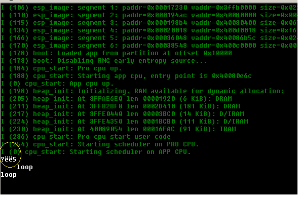
the output:
i change the code then with a delay for enough time give for setup the peripherals
//file: main.cpp
#include "Arduino.h"

void setup(){
  Serial.begin(115200);
  delay(500);
}

void loop(){
  Serial.println("loop");
  delay(1000);
}
the output is little better only one character on begin sucks

i try then few things but this one character goes not away
//file: main.cpp
#include "Arduino.h"

void setup(){
  Serial.begin(115200);
   delay(5000);
}

void loop(){

  delay(5000);
  while (-1) {
   Serial.println("loop");
   delay(1000);
  }
}
but this character sucks allways again


the character is 0xFF ( on baud 115200 )

from where this character comes?
which task has this sign?
why is it here?
can we eliminate it?
thanks
best wishes