Hello thereeee
This is a site for me to document my current ongoing project a low profile wireless mechanical keyboard. Originally started this a few years ago back when I was in middle school (my macbook air had a semi-broken keyboard and I was just getting into the world of mechanical keyboards, AND there was a new set of low profile mechanical switches on the market)
But who even knows anything about electronics engineering at that age? Took me a few years and attempts to slowly figure stuff out (you can see where I got to in my last attempt here, made when I was in G10: https://github.com/iamjackchen/ProjectGhostboard-OLD-)
Enough with the history, moving onto the project itself. The original design goal was to build a low profile (i.e. portable) mechanical keyboard. The portable aspect also prompted me to pursue Bluetooth functionality which might have possibly been the worst decision I have ever made in terms of trying to actually finish this project.
Here were my original design blueprints:
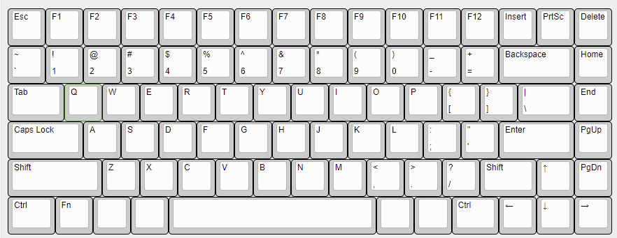
The design has evolved a little (along with my knowledge of embedded systems and keyboard assembly 😂) but the general principle remains the same. A 75%-ish layout with PCB-mounted low profile switches (PG1350 - I'm using the brown/tactile variant) and white multi-level backlight. No disgusting rgb. Originally when the PG1350 line was released I tried to make this the first true low-profile wireless keyboard on the market but obviously that didn't happen lmao. The layout I eventually settled for is below:
The current PCB design (in the electronics folder) uses a USB-power gated MOSFET to regulate power delivery from the battery to the main circuit, an MCU-gated MOSFET to control charging (power flow to the battery) and a MCU-gated MOSFET to trigger Bluetooth. The intention of the MCU-gated control charging MOSFET is for the user to be able to disable charging when the keyboard is being plugged in over long periods of time for battery longevity. I'll probably use raw-hid to have some sort of computer-keyboard communication and write a desktop client that can tell the keyboard to disable charging. Maybe in the futre I can use raw-hid and a desktop client for other purposes (macros, backlight settings, and etc)
Some other design considerations and features with regards to electronics:
- USB Type C
- Battery charge indicator
- HID over BLE
The software that makes all of this come together is QMK. It's a keyboard firmware written in C and I am immensely grateful to its creators. And yes, for all new programmers here, do learn C or C++ before Python and not the other way around. You will thank me.
I havent gotten far enough to worry too much about the physical enclosure and keyboard assembly but I will have (hopefully) some CAD files, screenshots, and renders hanging out in this repo soon!! As of now I am aware that the PG1350 requires a thinner (1.2mm) plate and the stabilisers are mounted to the PCB (with plate cutouts needed).
If you've read this far, thank you so much for taking interest, and I hope to bear good news of progress soon. Below is a gallery of certain snippets from this awesome journey.
Stay tuned.
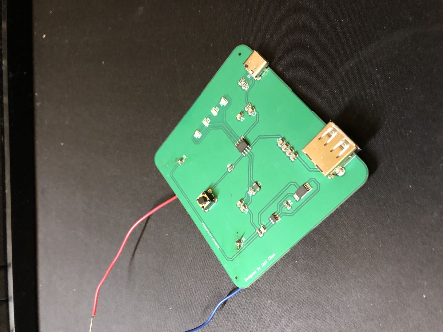
Small PCB to test out my USB-C power delivery designs. Used an IC originally meant for power bank charging (IP5306 if anyone's interested) along with an FS8205A and a DW01 for battery surge protection. I had a lot of trouble soldering on header pins so I stripped two wires for it. Janky? Yes. But it works 😂
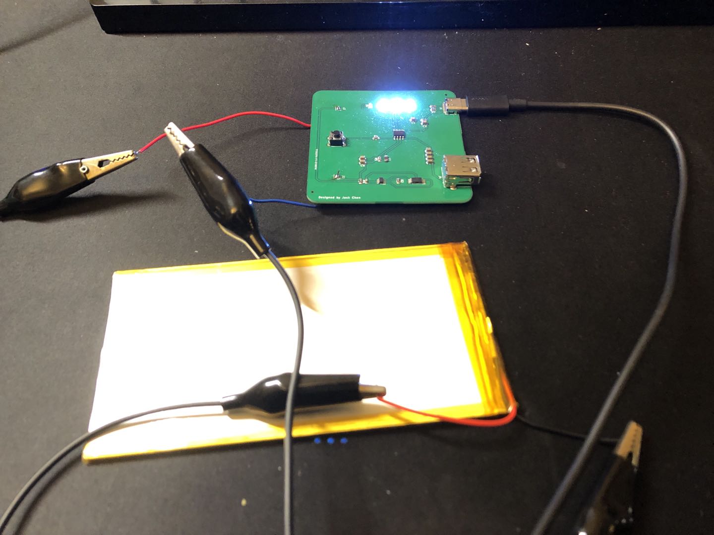
Here's it in action with a 4000mAh lipo I had lying around from the last attempt at making this keyboard:
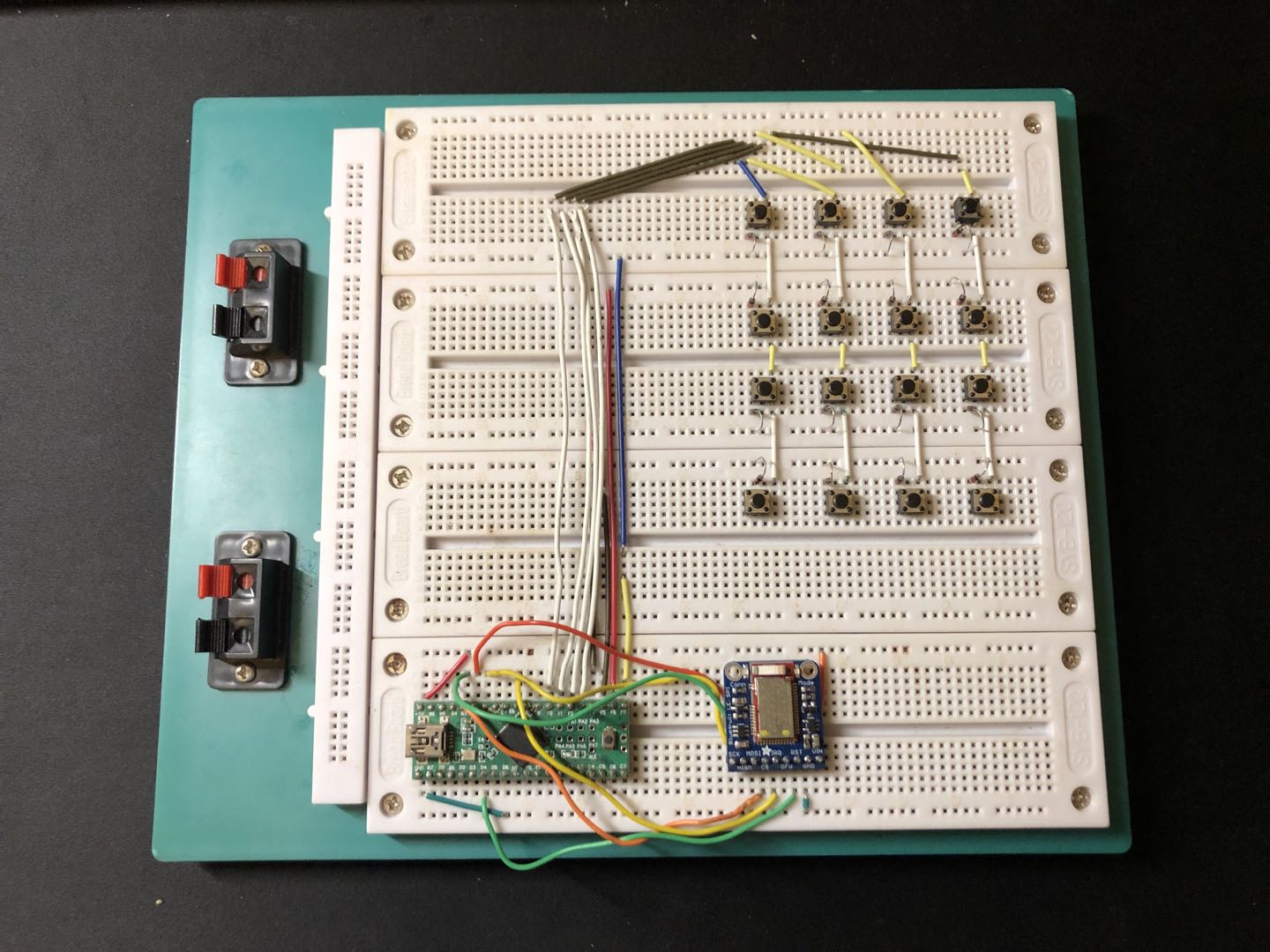
This is a demo of a proof of concept that my parents made me build before they would sponsor any further work of a custom PCB. On the breadboard I have a Teensy2.0++ (ATUSB1286, the MCU I use in my custom PCB) wired to an Adafruit BLE module via SPI and a 4x4 tester matrix of generic buttons. I built this a while ago but lost the original video so I filmed it again a few days ago. Starring Antoni's new M1X MBP.


