NodeMCU, Lua, HC-05 Bluetooth LE, DHT11 Humidity and Temperature sensor
Exploring NodeMCU (ESP8266, ESP-12E), Lua, HC-05 Bluetooth transceiver module, and DHT11 Humidity and Temperature sensor
What I'm doing here is sending a command from my phone, via Bluetooth, to a WiFi module, telling it to read temperature and humidity data and publish that data to a topic brokered by a CloudMQTT account.
I did most of the work on Linux Ubuntu 18.04. The flash program is designed for Windows and did not work correctly with WINE.
You will need to do the following:
- Acquire a NodeMCU V1.0, preferably the Amica variety. Other manufacturers have a different pin layout, so you'll need to figure out what that is if you choose a different OEM. Amica is "officially supported" by the way. No matter what the OEM, the boards are typically around $5-10 USD.
- Acquire an HC-05 Bluetooth module. These are typically around $4 USD.
- Acquire a DHT11 Humidity and Temperature sensor, around $3-7 USD. Mine is made by Osepp, called a HUMI-01, with 3 pins instead of 4 (no NULL pin).
- Setup a free account at CloudMQTT. The free tier is called Cute Cat.
- Download and install the NodeMCU Firmware Flasher. The github project is called nodemcu-flasher and you can get it here. It's designed for Windows and so I used it on Windows. I can't really testify whether it works well on Linux, as I was not setting the jumper correctly at the time. More on that later...
- Download and install esplorer
- Know your docs. For help you'll want to look in the following places:
- For NodeMCU, go to the official docs
- For Lua, lua-users.org has been the most helpful to me, but official docs are at lua.org.
- CloudMQTT has an API with docs
- For specifically joining NodeMCU and HC-05 I went here (in fact this project is largely based on this link)
- Learn to read schematics here
- Acquire a 5V power source that you can wire up to the HC-05. For me the easiest thing was an Arduino Uno board.
- You'll also need some basic prototyping tools, like wires, a 330 ohm resistor, an LED, and a breadboard.
- Download and install BT Terminal on your smartphone. I use an Android phone. As you might guess, the BT in BT Terminal stands for BlueTooth.
- Go to nodemcu-build.com and select the following modules for your firmware build:
Bloom filter, crypto, CoAp, DHT, file, GPIO, I2C, net, node, timer, UART, WiFi, MQTT, SPI, SJSON, websocket
(Disclaimer: I don't use all these modules, but I plan to. If you are doing something different with this project, you
can choose which modules you need; the build site has tooltips for each module explaining what it is, and each module is
documented well in the resouce listed above.)
- Also be sure to choose TSL/SSL, but no debug. Debug will take up a large amount of resources on the chip.
- Branch should be the master branch.
- Enter an email to receive the build and then wait for your custom build to be built.
- More instructions
- As a last resort, if you have trouble with your build you can use the one provided in the project.
There are a number of other tools I could have used, but didn't. They are:
- esptool
- luatool
- Arduino (for writing code, I still use it for powering the HC-05)
- MicroPython
- any of the other ESP8266 boards (ESP-1, etc)
- MQTTfx, or node-red, or a number of other programs capable of brokering MQTT transmissions
I also recommend getting more than one NodeMCU and HC-05 module, as the likelihood of getting 2 bad chips is pretty slim. Out of 4 NodeMCUs I purchased, one was toast.
You will need a wire for this, a short one will do. I tried running the flasher on WINE but I'm not confident I had the wire on the correct pin at the time. Since then I've run this on a Windows machine (Win 8) and it never fails. On an Amica board, wire the D3 pin to ground when flashing. Beyond that, follow the instructions here. I did not use the NodeMCU dev kit but it might help you. From here on, I'm using a Linux Ubuntu desktop OS.
First put your NodeMCU on a breadboard toward the bottom. On a small breadboard with rows numbered from 1 to 30, I put it between 30 and 16, with a column of holes on either side. The exact location on the breadboard isn't terribly important, just convenient, since we'll be filling up the breadboard with other things and we'll need to make room. If you'll be following my pin-to-hole placement instructions in Step 5, the board should be at those rows, with an open column on either side (a1-a30 and j1-j30).
The NodeMCU connects via micro-USB. Open esplorer, and expand it if you need to. The app has two sides, with code editor and dev tools on the left, and serial monitor on the right. On the code editor, keep it on the "NodeMCU & MicroPython" tab and open the credentials.lua and init.lua files.

Your computer should be on a wifi network (as opposed to wired, which I often do). In the credentials file, the SSID and PASSWORD should be the same as what your computer is connecting with. It's probably a good idea to change the CLIENTID to something custom, since the value of node.chipid() may not be different between physical chips (at least not the 3 working ones I bought).
The IPADR will be a static IP that you request for the NodeMCU module. On Linux, type ifconfig | grep "inet 192.168.". You may see a few IPs starting with 192.168, and these are IPs you should not set as the value for IPADR. For me, 192.168.1.5 is usually always available (i.e., not shown in the list and not assigned to anything else the router is connected to).
IPROUTER should be 192.168.0.1 unless you've manually changed it on your router, in which case you probably have a better idea what's going on here than I do.
NODEIPADR and NODEIPROUTER can be skipped for now; I haven't yet implemented the private access point.
Log into your CloudMQTT account, go into your free tier server, and go to the Details tab. In the credentials file:
- BROKER is the Server address
- BRUSER is the User name
- BRPORT, SSLPORT and SOCKPORT are the Port, SSL Port and Websockets Port, respectively
- BRPWD is the Password
On the right-hand side of esplorer, at the top, you should see a dropdown of serial connections. If none of those have USB in the name (on Windows it will be COM3), hit the button with the recycle symbol on it (the hover text says "Scan system for available serial port") and it should appear. Next, pay close attention to the two buttons labelled DTR and RTS. DTR means Data Terminal Ready and RTS means Request to Send. You want these both off while the connection is closed; starting with them on causes weird hiccups and they'll need to be turned off and on again. For me, the sequence seemed to matter a bit: RTS first, then DTR. In fact, I often turn both off and on in that order while connected, to reboot the chip.
Hit the Open button.
You should get a success message for the communication to the chip, but a failure message for a missing init.lua file. On the left hand side, toward the bottom, you'll see an Upload button. Hit that, multi-select the credentials and init files, and send them over to the chip. Then reboot it. If all goes well here, you can upload the rest of the files we'll be using. That doesn't include all the files in the project, so the list is as follows:
- disconnect_mqtt.lua
- disconnect_webserver.lua
- nodemcu_ble_led.lua
- nodemcu_dht_read.lua
- nodemcu_mqtt_publish.lua
- parse_mqtt_err_reason.lua
- switch.lua
- webserver.lua
- wifi_servers.lua
- wifi_station.lua
After these are on the NodeMCU, close the connection, turn DTR and RTS off, and unplug the NodeMCU from the computer.
The breadboard I describe below is a shorter type with 30 holes per column. Your breadboard should have side rails with +/- for positive and negative (ground). If not, you'll need to find one. These rails don't line up exactly with the grid between the rails, so the coordinates I give below for any hole in positive or negative will be numbered according to their actual number in sequence going down the board. Also, despite that I will specify holes on the positive/negative rail, you can place wires in any hole on that rail and it will be fine. Similarly, the specific placement of the hardware on the board is solely for you to reproduce what I've done with minimal error.
This is where the ability to read a schematic comes in handy. All I had to work with was this schematic: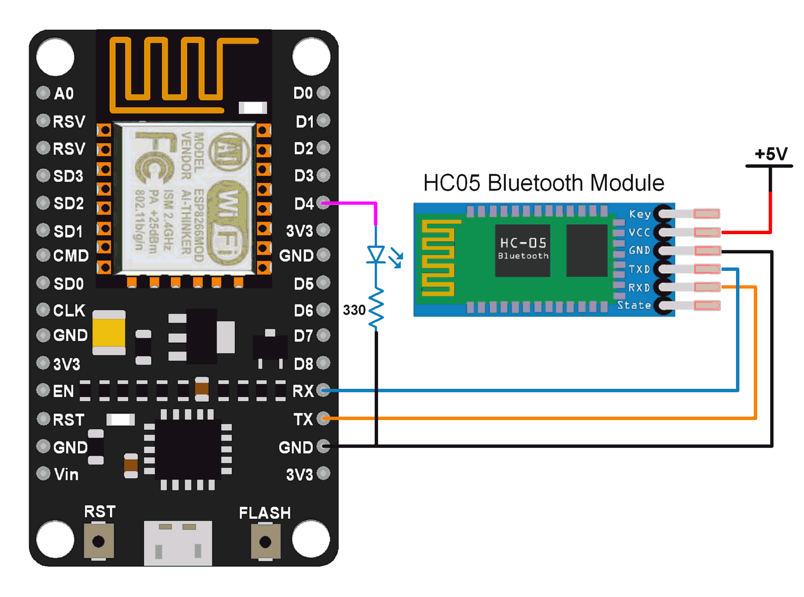
If you want explicit instructions, here's how my breadboard is wired:
-
Place the LED on the board at holes f11 and f12, with the negative (shorter) pin in f11.
-
Place a 330 ohm resistor with each end in g11 and g10.
-
Place the HC-05 Bluetooth at holes f1 through f6, with the KEY or EN pin at f1 and the STATE pin at f6. This places the VCC pin (Voltage Common Collector, aka the power input) at f2, GND (ground) at f3, TXD (transmit) at f4, and RXD (receive) at f5.
-
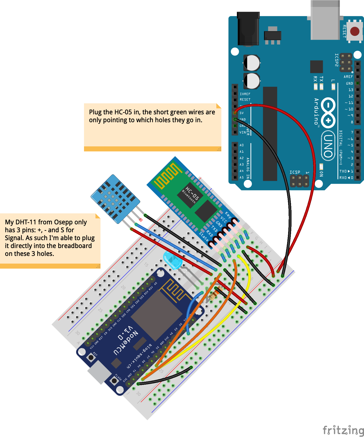
Place the DHT11 Humidity and Temperature sensor to the following holes. Your module may differ, including having 4 pins instead of 3 -- rearrange pins/wires to accomodate your setup if you can plug directly in. On my Osepp HUMI-01 (another sensor based on DHT11), there are 3 pins instead of 4. Since I can plug this directly into the breadboard next to the Bluetooth, the pins will be ordered positive, negative and signal, with negative at f9, positive at f8, and signal at f7. The holes to connect the DHT11 are:
- DHT11 GND (-) to f7
- DHT11 Signal (S) to f8
- DHT11 VCC (+) to f9
On my 3-pin Osepp board, it goes:
- HUMI-01 GND (-) to f9
- HUMI-01 VCC (+) to f8
- HUMI-01 Signal (S) to f7
-
Attach wires between the following pairs of holes:
-
HC-05 Bluetooth
- +2 to g2 (power from positive to power input)
- -2 to g3 (ground to ground)
- g4 to j27 (Bluetooth TXD to NodeMCU RXD)
- g5 to j28 (Bluetooth RXD to NodeMCU TXD)
-
DHT11 Humidity and Temperature sensor
- g8 to j25 (DHT11 Signal (S) to NodeMCU D7 pin) OR Osepp Humi-01
- g7 to j25 (3-pin DHT11 Signal (S) to NodeMCU D7)
-
LED
- h10 to -8 (330 ohm resistor to ground)
- g12 to j18 (LED positive pin to NodeMCU D2 pin)
- j29 to -22 (NodeMCU ground to ground)
-
5V power -- I use an Arduino Uno board, because it has power outputs that are simple to wire. A regular 5V power supply with a single cord and barrel-tip connector won't help, unless you're powering an Arduino (or similar) board.
- Arduino 5V to breadboard +1
- Arduino GND to breadboard -1
-
Open the nodemcu_mqtt_publish.lua file in esplorer. In the publish function you can see where MQTT will be sending sensor data from the DHT11 Humidity and Temperature sensor to the CloudMQTT server. As of this writing, CloudMQTT has enforced a rule where you must specify the ACL rules and topics you'll be publishing and subscribing to. The free tier also has a limit of 5 rules, and we'll use 3 of them.
Go back to your CloudMQTT account and visit the Users & ACL tab. There are 2 categories of ACL rules, Pattern and Topic. Both define the topic that you can publish/subscribe to. The difference is simply that Topic restricts access to the topic to a specific user. For example, for the same topic pattern, you may want User A to have read/write, while User B only has read. We don't care about that now, so Pattern is fine. The patterns I defined in my account are reflected in the nodemcu_mqtt_publish.lua publish function, so if you make your own patterns, you'll need to update your publish function to match it. These patterns are:
- pattern /sensors/ESP8266-1093336/temperature true/true
- pattern /humidity/ESP8266-1093336/humidity true/true
- pattern /sensors/ESP8266-1093336/errors true/true
Now go to the Websocket UI tab. Send yourself a message to one of the topics to verify things are working ok with the vendor.
Reconnect the NodeMCU to the computer, but do not power the Bluetooth (unplug the 5V power source, but not the wires going to the breadboard). The reason is once the Bluetooth is powered and interacting with the NodeMCU, the NodeMCU will not be able to accept any more commands from you, and we need to do one more thing first. I purposely omitted any dofile commands in the setup function in init.lua. If something is wrong with any of those files, it will be difficult to upload a fix to the chip. Instead, we'll hit the Reload button in the right-hand panel on the right-hand side of esplorer. This will give us a list of files loaded on the board in the form of buttons (you may have to stretch the window out to reveal it). Clicking any of these buttons will run the file.
- Click the nodemcu_ble_led.lua file.
- The serial monitor should print "Writing to pin 2" and now the program is running ongoing. At this point, you can no longer interact via esplorer except to restart or close it. Other actions will result in an error message saying "Timeout reached. Command aborted." One thing I'd like to point out here is that pin 2, the chosen pin to connect to the LED, does not conform to the instructions I was following. I'm not sure if it's because pin layouts are different between NodeMCU manufacturers, but I noticed that in the NodeMCU pinout diagram
, the D4 pin is labeled GPIO2, and D2 is labeled GPIO4. The wire is connected to D2 but setting LEDpin to 4 like the instructions say did not work. LEDpin = 2 does work.
- The serial monitor should print "Writing to pin 2" and now the program is running ongoing. At this point, you can no longer interact via esplorer except to restart or close it. Other actions will result in an error message saying "Timeout reached. Command aborted." One thing I'd like to point out here is that pin 2, the chosen pin to connect to the LED, does not conform to the instructions I was following. I'm not sure if it's because pin layouts are different between NodeMCU manufacturers, but I noticed that in the NodeMCU pinout diagram
- Power up the Bluetooth via Arduino board
- Open Bluetooth settings on your phone, search for one named HC-05 and connect with default password 1234.
- Sometimes the name won't show, only the address. The address usually starts with 98:D3. If you can't find it, open the Bluetooth settings on your computer. On Ubuntu, the list of Bluetooth devices it can see shows the HC-05 name. After connecting to a few different HC-05 chips, I see them all in the list, but with the same name. Clicking on the device while it's powered and looking to be found will give us an opportunity to connect with the default password. Now when you click on the device you can see what the address is. Back on your phone's Bluetooth settings, look for that address and connect via password. This makes your phone aware of that device even after it disconnects.
- Open BT Terminal on your phone and hit Connect.
- You should now see HC-05 in the list of devices. Click on it to connect and be taken back to the main screen.
- Now type the number 1 on the line and hit Send, while watching the Websocket UI tab of your CloudMQTT account.
- 2 received messages should come in, for humidity and sensors topics. The LED on the breadboard should be lit up. You should be impressed.
- Also, the BT Terminal app should receive several lines of text including the temperature and humidity values the NodeMCU received from the DHT11, and the state of the LED (on or off).
- Type the number 2 on the line and hit Send.
- This closes the connection on the NodeMCU MQTT client, and turns the LED off.
