-
Notifications
You must be signed in to change notification settings - Fork 4
Digital Control of Motor Current
Peter Kazanzides edited this page Apr 19, 2021
·
9 revisions
This page contains instructions for modifying a QLA board to enable digital current control on the FPGA, rather than via analog hardware.
DO NOT FOLLOW THESE INSTRUCTIONS UNLESS YOU REALLY KNOW WHAT YOU ARE DOING!
Incompatibilities between the hardware and firmware or incorrect hardware modifications can lead to destruction!
Note that digital current control requires an updated firmware, which is currently available in the feature-digital-control branch of the mechatronics firmware. There is a corresponding feature-digital-control branch of the mechatronics software repository.


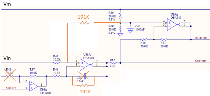
- Remove R46
- Short R47
- Do one of the following:
- Replace C74 (100 nF) by 191 kOhm (if SMD resistor available)
- Remove C74 (100 nF) and insert 191 kOhm between pins 1 and 3 of the op amp U38A (if THT resistor available)
- Insert 191 kOhm from U38A pin4 (non-inverting terminal) to U39A pin 4 (non-inverting terminal), best done on the backside

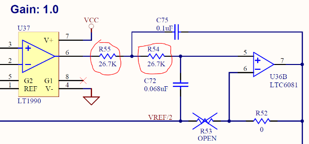
- Replace R54 by 39 Ohm
- Replace R55 by 39 Ohm