-
Notifications
You must be signed in to change notification settings - Fork 68
Controller Boxes
For all acronyms see FAQ.
Each da Vinci arm (MTM, PSM, ECM) is controlled by a single box, shown below. A similar controller box is used for the Setup Joint controller (see below). The controllers are built around 2 QLA/FPGA stacks. They are designed to interface with the da Vinci Classic (first generation) active arms, both on the patient and surgeon's side. They provide inputs for the potentiometers and encoders as well as miscellaneous digital IOs (foot pedals, buttons...). For motor control they use linear amplifiers with current feedback. All controllers come with FireWire interfaces so they can be daisy chained and communicate with a computer. Later controllers came with an Ethernet adapter (supported with firmware 7+ and software 2+). See also controller versions.
- One AC power connector, with on/off switch
- One 156-pin connector (for the MTM, PSM, or ECM)
- Two FireWire connectors
- Two Ethernet connectors (later versions)
- One or two 4 or 5-pin safety chain connectors (depending on version); see ESTOP page
- One DB15 footpedal connector; see dMIB I/O page
- Seven HD15 expansion connectors and one HD26 expansion connector; see dMIB I/O page
Internally, each controller box contains two FPGA/QLA board sets, one dMIB (da Vinci Manipulator Interface Board), LED boards, power supplies and relays.

- Component versions by build/date.
- The FPGA and QLA designs are open source and available via this GitHub page.
- The dMIB is provided by Intuitive Surgical. The designs, including schematics and BOM, are available via this GitHub page.
- All boxes contain a 12V (50W) logic power supply that provides power to the FPGA boards and the safety chain.
- Each box also contains one or more motor power supplies that are connected to the QLAs:
- MTM: one 24V (75W) power supply connected to QLA #1 and one 12V (50W) power supply connected to QLA #2
- PSM: one 24V (225W) power supply connected to both QLAs
- ECM: one 36V (225W) power supply connected to both QLAs
- Replacement power supplies
- 12V Logic Power Supply (For All) & 12V Motor Power Supply (For MTM): https://www.digikey.com/product-detail/en/cui-inc/VGS-50-12/102-1935-ND/2045666
- 24V Motor Power Supply (For MTM): https://www.digikey.com/product-detail/en/cui-inc/VGS-75-24/102-1943-ND/2045674
- 24V Motor Power Supply (For PSM): https://www.astrodynetdi.com/ecatalog/power-supplies/PMK225S-24U
- 36V Motor Power Supply (For ECM): https://www.astrodynetdi.com/ecatalog/power-supplies/PMK225S-36U
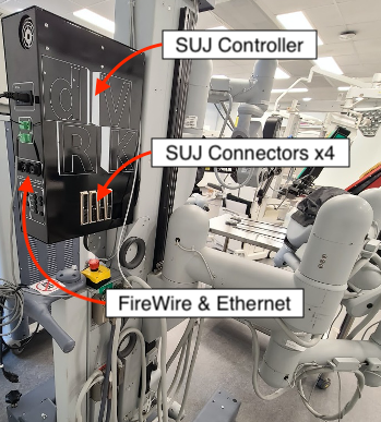
The dVRK SUJ controller supports all the features available on the daVinci patient cart, i.e.:
- Read joint positions. The dVRK QLA has 4 analog to digital inputs so it reads the potentiometer values sequentially using a multiplexer.
- Release brakes. The dVRK controller uses the linear amps of the QLA dedicated to motor control to release the brakes.
- Lift PSM3. The dVRK FPGA generates a PWM signal sent to the PWM power unit included on the dSIB.
For more details regarding the software features and configuration, see the SUJ page.
- One AC power connector, with on/off switch
- 4 156-pin connectors (one per SUJ arm)
- Two FireWire connectors
- One Ethernet connecttor
- Two 5-pin safety chain connectors; see ESTOP page

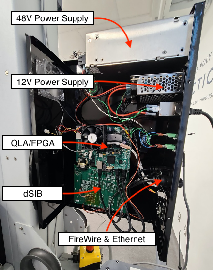
Internally, each controller box contains one FPGA/QLA board set, one dSIB (da Vinci SUJ Interface Board), LED boards and 2 power supplies:
-
12V (50W) logic power supply that provides power to the FPGA board
-
Brake power supply connected to the QLA (48V)

Community
Getting Started
- First Steps
- Software installation
- Controller Connectivity
- Configuration files
- Hardware Setup
- Calibration
- Classic/Standard
- Si
- Examples
Advanced
- Software Architecture
- Application Development
- APIs
- UI Customization
- Teleoperation
- Kinematics Simulation
- Potentiometer Issues
- Development Branches
- Release Checklist
- Projects
- Controllers/versions
- E-STOP Wiring
- Full da Vinci System
- Head Sensor
- Foot Pedals
- Video
- Instruments
Miscellaneous
- Frequently Asked Questions
- User manuals Classic and Si moved
- QLA Heat Sink
- Build w/o ROS Linux Mac
- cisst
- JHU
Deprecated
