Hardware Mods
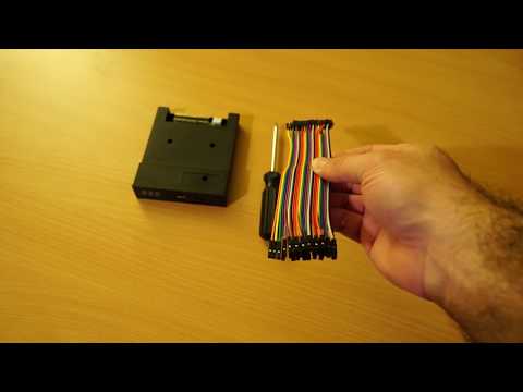
Most modifications simply involve plugging new hardware add-ons into pin headers on the Gotek PCB. The PCB layout is summarised below. We will refer to this diagram for each hardware mod.

A speaker can be attached to the Gotek to sound whenever the drive heads move. The simplest method is to connect a piezo sounder directly to the JB header pins.

There is also a step-by-step video describing this mod:
If you want to connect a magnetic speaker instead, you must buffer via an NPN transistor. If you don't know what this means just be sure to use a piezo sounder, easily found on Ebay, and connect it directly as shown above.
FlashFloppy supports a third button in addition to the basic up/down controls. This should be a standard momentary microswitch, connected to the header pins JA.
The button's effect depends on the current state of operation:
- When an image is loaded, the button will immediately eject it
- When selecting an image, the button will immediately confirm the currently-selected image
As an alternative to the Gotek 7-segment display, FlashFloppy supports the ubiquitous two-row LCD with I2C backpack board. These are available from many Ebay sellers in compatible sizes from 16x2 up to 40x2 characters.
You can locate the required connections on your Gotek PCB as below. These connect to the corresponding header pins on your LCD I2C backpack module.

The SCL and SDA lines must be connected to VCC ("pulled up" to VCC) via 4.7k resistors. Note that many I2C boards have the pullup resistors on board and in this case you do not need to attach your own external pullups. You can confirm this by checking the resistance between SDA/SCL and VCC. If it is less than 10k you do not need to add pullups.
If you do require the pullup resistors, these can be soldered to the backside of the Gotek PCB between VCC and each of SDA and SCL. Alternatively the resistors can be soldered to the back of the I2C module header.

Another alternative to the Gotek 7-segment display is a 0.91" 128x32 display, as sold for Arduino projects by many Ebay sellers. You will require a display with I2C interface: you should see it has a 4-pin header marked GND, VCC, SCL, SDA.

These displays can simply connect to the 7-segment display's header, reusing the existing jumper wires.

I2C 128x64 monochrome displays are also compatible. The usual sizes
are 0.96" and 1.3". The 1.3" size needs a line in FF.CFG:
display-type = oled-128x64-sh1106.
As an alternative to using the up/down buttons you can instead connect a rotary encoder. The pictures below show how to connect it, either directly or via a PCB module (eg KY040).
When connecting via a PCB module, you may need to connect to 3.3v if the board has pull-up resistors mounted.

If connecting directly note that by convention GND is always the middle pin in the row of three. If there is a further row of two pins then these are connected to an internal push switch: you can wire these pins to jumper JA to use the switch as an eject/select button.

Rotating the dial should now have the same effect as pushing the buttons: anti-clockwise for down, and clockwise for up.
Troubleshooting:
- Directional controls are inverted: swap the A and B (aka CLK, DT) wires.
- Four clicks are required to move a single step: specify
rotary=grayin FF.CFG - PCB modules only: Both directions move up (or down):
- Connect + to 3.3V (marked in picture above); or
- Remove pull-up resistors from the back of the PCB; or
- Remove the encoder from the PCB and solder wires directly.
Gotek clone designers can choose to add various enhancements to the standard Gotek, all supported by the FlashFloppy firmware. Note that these instructions are intended for PCB designers and cannot be retrofitted to a standard Gotek without fine soldering skills. Regular Gotek users should therefore skip this section.
- PC12-15: Board Identifier
- PA3: Second Drive Select
- PA15: Motor-On Signal
- PA4-5: USB Power Switch
Pins PC12-15 are used to identify an enhanced Gotek. On a standard Gotek board these pins are disconnected and floating. On an enhanced Gotek they should all be connected to VSS (GND).
FlashFloppy may in future emulate two drives in a single Gotek. To support this pin PA3 may be connected to a second drive-select line and pulled up by 1K to VCC (5v). If second-drive select is not supported then the pull-up is still required, to avoid PA3 floating.
FlashFloppy may in future use the motor-on signal to improve emulation accuracy. To support this pin PA15 may be connected to the motor-on line (eg floppy pin 16) and pulled up by 1K to VCC (5v). If the motor-on signal is not supported then the pull-up is still required, to avoid PA15 floating.
A power switch with active-low enable and open-drain fault output may be connected as follows:
- PA4: active-low enable (output to USB power switch)
- PA5: open-drain active-low fault signal (input from USB power switch)
These connections are optional and either pin may instead be left disconnected and floating (the STM32 will pull them to a defined level).
A suitable power switch is STMicroelectronics STMPS2141.