Hardware Mods
- Board Layout
- Speaker
- Select/Eject/Insert Button
- LCD Display
- OLED Display
- Rotary Encoder
- Blackberry Trackball
- Motor Signal
- Disk Change Reset
- Enhanced Gotek
Most modifications simply involve plugging new hardware add-ons into pin headers on the Gotek PCB. The PCB layout is summarised below. We will refer to this diagram for each hardware mod.

Certain modifications attach to the Gotek programming header, which has the layout indicated below. Please note that some Gotek revisions do not have all header pins available.

A speaker can be attached to the Gotek to sound whenever the drive heads move. The simplest method is to connect a piezo sounder directly to the JB header pins.

There is also a step-by-step video describing this mod:
The disadvantage is that piezo sounders are often too quiet. Instead you can attach a magnetic speaker or 5v active buzzer (easily found on Ebay) using the following circuit:

This attaches to the Gotek at 5v, Ground and JB, all of which are available at header pins, and are easily connected or soldered to (see the Board Layout, and note that the right-hand pin of the jumper row marked JB is Ground).
Also known simply as the Select button, FlashFloppy supports a third button in addition to the basic up/down controls. This should be a standard momentary microswitch, connected to the header pins JA.
The button's effect depends on the current state of operation:
- When selecting an image, the button will immediately select the currently-selected image
- When an image is inserted, the button will immediately eject it
- When an image is ejected, the button will immediately insert it
As an alternative to the Gotek 7-segment display, FlashFloppy supports the ubiquitous two-row LCD with I2C backpack board. These are available from many Ebay sellers in compatible sizes from 16x2 up to 40x2 characters.
You can locate the required connections on your Gotek PCB as below. These connect to the corresponding header pins on your LCD I2C backpack module.

The SCL and SDA lines must be connected to VCC ("pulled up" to VCC) via 4.7k resistors. Note that many I2C boards have the pullup resistors on board and in this case you do not need to attach your own external pullups. You can confirm this by checking the resistance between SDA/SCL and VCC. If it is less than 10k you do not need to add pullups.
If you do require the pullup resistors, these can be soldered to the backside of the Gotek PCB between VCC and each of SDA and SCL. Alternatively the resistors can be soldered to the back of the I2C module header.

Another alternative to the Gotek 7-segment display is an OLED display, as sold for Arduino projects by many Ebay sellers. You will require a display with I2C interface: you should see it has a 4-pin header marked GND, VCC, SCL, SDA.

These displays can simply connect to the 7-segment display's header, reusing the existing jumper wires.

Supported screen resolutions are 128x32 and 128x64. These come in some common sizes:
- 128x32: 0.91", 2.23"
- 128x64: 0.96", 1.3", 2.42"
Note that the larger 2" displays are typically configured for SPI and will need circuit changes to configure for I2C:
- Usually a resistor must be removed or relocated
- Usually one or two empty resistor locations must be bridged with solder
- CS and DC pins must be connected to ground
- RES(ET) pin must be connected to 3.3v
Additionally, the 2.23" 128x32 display will typically need explicit
configuration in FF.CFG to avoid a mangled display output:
display-type = oled-128x32-ztech.
As an alternative to using the up/down buttons you can instead connect a rotary encoder. The pictures below show how to connect it, either directly or via a PCB module (eg KY040).
When connecting via a PCB module, you may need to connect to 3.3v if the board has pull-up resistors mounted.

If connecting directly note that by convention GND is always the middle pin in the row of three. If there is a further row of two pins then these are connected to an internal push switch: you can wire these pins to jumper JA to use the switch as a Select/Eject/Insert button.

Rotating the dial should now have the same effect as pushing the buttons: anti-clockwise for down, and clockwise for up.
Troubleshooting:
- Directional controls are inverted: swap the A and B (aka CLK, DT) wires.
- Four clicks are required to move a single step: specify
rotary=grayin FF.CFG - PCB modules only: Both directions move up (or down):
- Connect + to 3.3V (marked in picture above); or
- Remove pull-up resistors from the back of the PCB; or
- Remove the encoder from the PCB and solder wires directly.
A neat alternative to a rotary encoder is the Blackberry-style miniature trackball. These can be found on Ebay and AliExpress for a few dollars. Unfortunately they are tricky to fit to a standard Gotek front panel due to the size of their PCB; however, they are an interesting option for custom designs.
Wiring is very similar to the PCB-based rotary encoder. With reference to the lines in the encoder's wiring diagram:
- VCC connects to 3.3V (dashed orange)
- GND connects to ground (black)
- BTN connects to JA (green)
- LEFT/RIGHT (or UP/DOWN) connect to the rotary pins (blue/red).
You will additionally require display-type = trackball in FF.CFG.
Here is a video demonstrating the trackball in action:
The new FF.CFG motor-delay option allows for emulation of correct
motor behaviour: the Gotek drive does not report it is 'ready' until some
milliseconds after it is ordered to spin up the drive motor.
However, standard Gotek does not internally connect to the motor signal, and the following modification is required to:
- Pull Gotek interface pin 16 up to 5v via a 1k resistor
- Connect Gotek interface pin 16 to STM32F105 pin 36 (PB15)
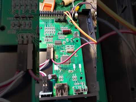
STM32 pin 36 is connected to pin 5 of the unoccupied SPI Flash footprint on the Gotek PCB. This is the easiest point to solder a wire to, as shown below:

The other end of this wire is soldered to pin 16 of the floppy header. A 1k resistor must also be soldered from pin 16 to the 5v rail. See below (the resistor is hidden in heatshrink tubing):

[v3.x Releases Only]
Although most drives reset their Disk Changed signal on receipt of a Step command, some older drives have an explicit Reset signal (eg. on pin 1 of some old Panasonic and Sony drives).
For disk changes to work correctly on hosts which use these old drives,
it is necessary to connect the Disk Change Reset signal to the Gotek's
microcontroller, and to configure support in FF.CFG:
chgrst = pa14
Cut the ground traces to floppy header pin 1. Solder a jumper wire from pin 1 to the SWCLK pin of the Gotek programming header (refer to Board Layout).
Create a custom ribbon cabkle with the following modifications at the Gotek connector:
- Separate wires 1-4 from the remainder (5-34).
- Separate wire 4 and cut it short (so it does not make contact)
- Separate wire 1 and bring it across to connect in place of wire 4.
- You now have a connector with pin 1 unused and pin 4 connected to wire 1.
The Reset signal is now present at Jumper J5 and can be connected to SWCLK via a Dupont jumper wire.
Gotek clone designers can choose to add various enhancements to the standard Gotek, all supported by the FlashFloppy firmware. Note that these instructions are intended for PCB designers and cannot be retrofitted to a standard Gotek without fine soldering skills. Regular Gotek users should therefore skip this section.
- PC12-15: Board Identifier
- PA3: Second Drive Select
- PA15: Motor-On Signal
- PA4-5: USB Power Switch
- PB12-15,PC9 SD Card Connector (optional)
Pins PC12-15 are used to identify an enhanced Gotek. On a standard Gotek board these pins are disconnected and floating; FlashFloppy internally pulls them high to identify an unenhanced board.
On an enhanced Gotek PC12-15 are selectively connected to VSS (GND). The four inputs PC[15:12] form a four-bit board identifier:
- 0000: Enhanced Gotek, no SD card connector
- 0001: Enhanced Gotek, with SD card connector
- 1111: Standard Gotek (no enhancements)
FlashFloppy may in future emulate two drives in a single Gotek. To support this pin PA3 may be connected to a second drive-select line and pulled up by 1K to VCC (5v). If second-drive select is not supported then the pull-up is still required, to avoid PA3 floating.
FlashFloppy may in future use the motor-on signal to improve emulation accuracy. To support this pin PA15 may be connected to the motor-on line (eg floppy pin 16) and pulled up by 1K to VCC (5v). If the motor-on signal is not supported then the pull-up is still required, to avoid PA15 floating.
A power switch with active-low enable and open-drain fault output may be connected as follows:
- PA4: active-low enable (output to USB power switch)
- PA5: open-drain active-low fault signal (input from USB power switch)
These connections are optional and either pin may instead be left disconnected and floating (the STM32 will pull them to a defined level).
A suitable power switch is STMicroelectronics STMPS2141.
An SD card connector may be connected as follows:
- PB12: SPI_CS (Chip Select)
- PB13: SPI_CK (Clock)
- PB14: SPI_MISO
- PB15: SPI_MOSI
- PC9: Card Detect
Card Detect should float when a card is inserted, and be driven low when no card is present. For simplest connection, this will require a card-detection switch which is open when a card is inserted, and closed when ejected. A switch with the opposite sense will require extra circuitry (eg. pull-up resistor and an open-drain MOSFET to invert the switch signal).