-
Notifications
You must be signed in to change notification settings - Fork 32
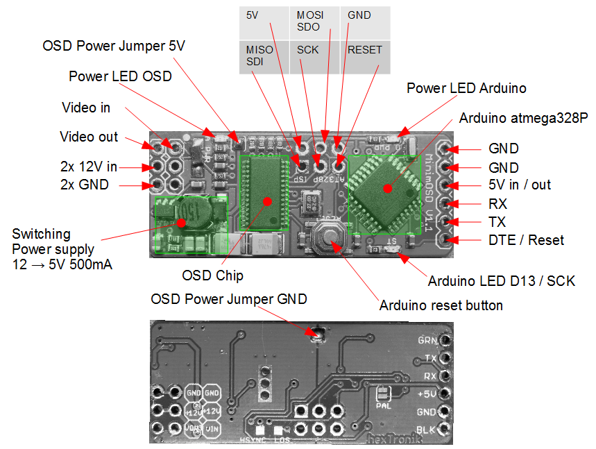
Anatomy of an minimOSD 1.x board

Out of the box the board has a connector with a UART / Reset / Power.
This is used to communication with a GPS or a flight control.
The very same port is used for Arduino upates via bootloader (if you have one ;-) ). The other side of the boad has the 12V input and the video In / out.
In the center there is the ISP port and you have a reset button and the "Pin 13 LED".
One special detail is the power supply of the board. You have 3 ways to use it:
-
Default configuration
12V for OSD and camera with inbuild 5V switching regulator.
5V for the Arduino is coming from copter control or GPS (external)
-
Solder the "two" bridges 12V
OSD and the Arduino are now on the same 5V
When you connect 12V to the input on the video side, the entire board is powered.
It has enough power to even power ~400mA for the GPS.
-
Solder the "two" bridges 5V
Same as the last configuration, but NO 12V is connected
The board is powered with 5V from the UART connector
The Pins on the UART connector can be used as GPIO.
Beside that the Pins on the ISP connector are also available. Nice detail: That is the SPI bus we need...
The options 2 and 3 are best for this project.