-
Notifications
You must be signed in to change notification settings - Fork 3
Documentation
See Releases for release history. The latest release is 3.0.0
This plugin adds a context menu for all operations. This are available using a menu right-click. The four operations provided by the plugin are under the FaceSVG submenu:
 .
.
The basic work-flow to use the plugin is to select individual faces representing the parts that will be cut, and doing Layout SVG Profile. After the desired SVG profiles have been created, they are then written into an SVG file with Write SVG Profiles. Settings can be used to control some elements of how the layout is done and control some elements of how the profile geometry elements are created.
❗️Note ❗️ Because the Layout SVG operation transforms face copies to
the z=0 plane, if your model already has geometry in the z=0 plane, the
result will cause unexpected intersections resulting in incorrect operation.
This can be avoided by moving all your model elements up, OR by ensuring that
your model elements are in groups or components which prevents Sketchup
from generating intersections.
It is deliberately a two step process - first, laying out the faces followed by writing them to SVG. The profile geometry elements that are created represent what the SVG will look like. But, importantly, they can be edited or reorganized to allow customizing how the generated SVG will appear, without requiring some OTHER software tool. Ideally, the FaceSVG Plugin can go straight from a model to SVG ready for use. As mentioned elsewhere, this plugin is intended primarily for generated output suitable for use with the Shaper Origin handheld CNC router (SO).
Since this is a Sketchup context menu, it will only be displayed when some element is selected or the mouse pointer is over some geometry element. Not all the items will be available all the time. See the discussion of the individual operations below.
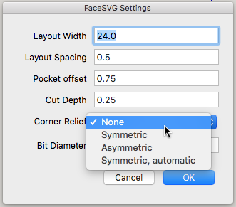
The Settings operation is always available. This displays the Settings that control different elements of the plugin's operation. A popup dialog is displayed with the available settings, with the current values. [1]
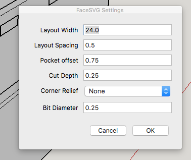
- Layout Width
The default for english units is 24". This setting is used to control the layout of multiple elements into a rectangular grid. As each face is selected and layed out, the faces are put into a horizontal row. Assume you are using a piece of material, say, 30" wide, and that you are building some structure composed of a series of 12" wide shapes. After two have been placed, the third - going past 36" - would be "off" the edge of your material. Now, with the SO, we can re-place the design for a later cut, but it is convenient to simply start a new row. Layout width provides for the ability to start a new row, when the layout width is reached.
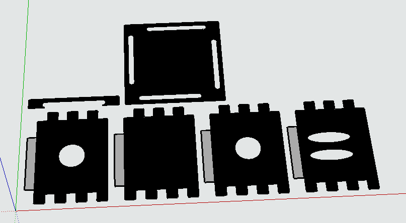
- Layout Spacing
The default for english units is 0.5". This is just the spacing between the different layed out face groups. This allows for the space for the cut for the desired bit.
- Pocket Depth (Max)
The FaceSVG plugin generates SVG for the SO with areas intended to be cut out as pocket cuts with a gray, area fill. See the appropriate SO documentation. It does this by detecting the faces connected to the selected surface face with the same orientation. In most cases this is unambiguous, but for complicated models this may match faces that are unrelated. Pocket Depth (Max) adds the additional constraint that the faces must be "nearby" -- within pocket depth. The default, 0.75", represents the deepest pocket that is desired (and is is a reasonable maximum since most material will be less than this.)
As a side note, setting this to 0.0 will effectively disable this pocket face detection, so that no gray fill areas will be generated.
- Cut Depth
The default is 0.25". There isn't much point to this. It adds an attribute shaper:cutDepth to exterior paths when the SVG is generated. This attribute is added by the official plugin provided by Shaper Tools, so may be recognized by the SO for some purpose. Currently it has no effect.
- Corner Relief and Bit Diameter
This is an advanced feature. The motivation for this can be seen in the video from Shaper Tools.

Because the goal of the FaceSVG plugin is to provide SVG that can be used directly in the SO tool, being able to generate these corner relief details in the generated SVG is provided as an option. By default, this option is set to None - no capability for corner relief is active. The three options for corner relief are Symmetric, Asymmetric, and Symmetric, Auto. Bit diameter is a parameter required for generating corner relief. See Corner Relief for an explanation of the capabilities for corner relief generation.
The Reset Layout operation is always available. As each face is layed out a copy of the face and its related faces are generated on the X Y plane (mostly) in the current model. These faces represent the SVG profile that will be generated, in a Sketchup group named SVG Profile Group. Reset Layout simply deletes this group, and resets internal layout information about where the next face will be layed out. Simply deleting the group, or using Edit->Undo will do the same thing except for resetting the internal layout information.
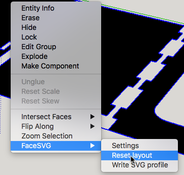
This is step 1 of the two step process of actually generating SVG output from your Sketchup 3D model. Simply select each face for which a cutting profile is desired. Right clicking with the context menu will select the face under the mouse and display the context menu in a single operation.
When a face on a surface is selected, the face and all the related faces are copied onto the XY plane in the current model. Pocket cuts are represented as faces at a depth below this plane. Each face is created in its own group, and all the groups are in a single Sketchup group. The faces in this group are converted into an SVG reperesentation as a separate step. This allows these faces to be edited from within sketchup before conversion to SVG. For example a rectagular cut representing a mortise slot could be edited from with Sketchup to include corner relief.
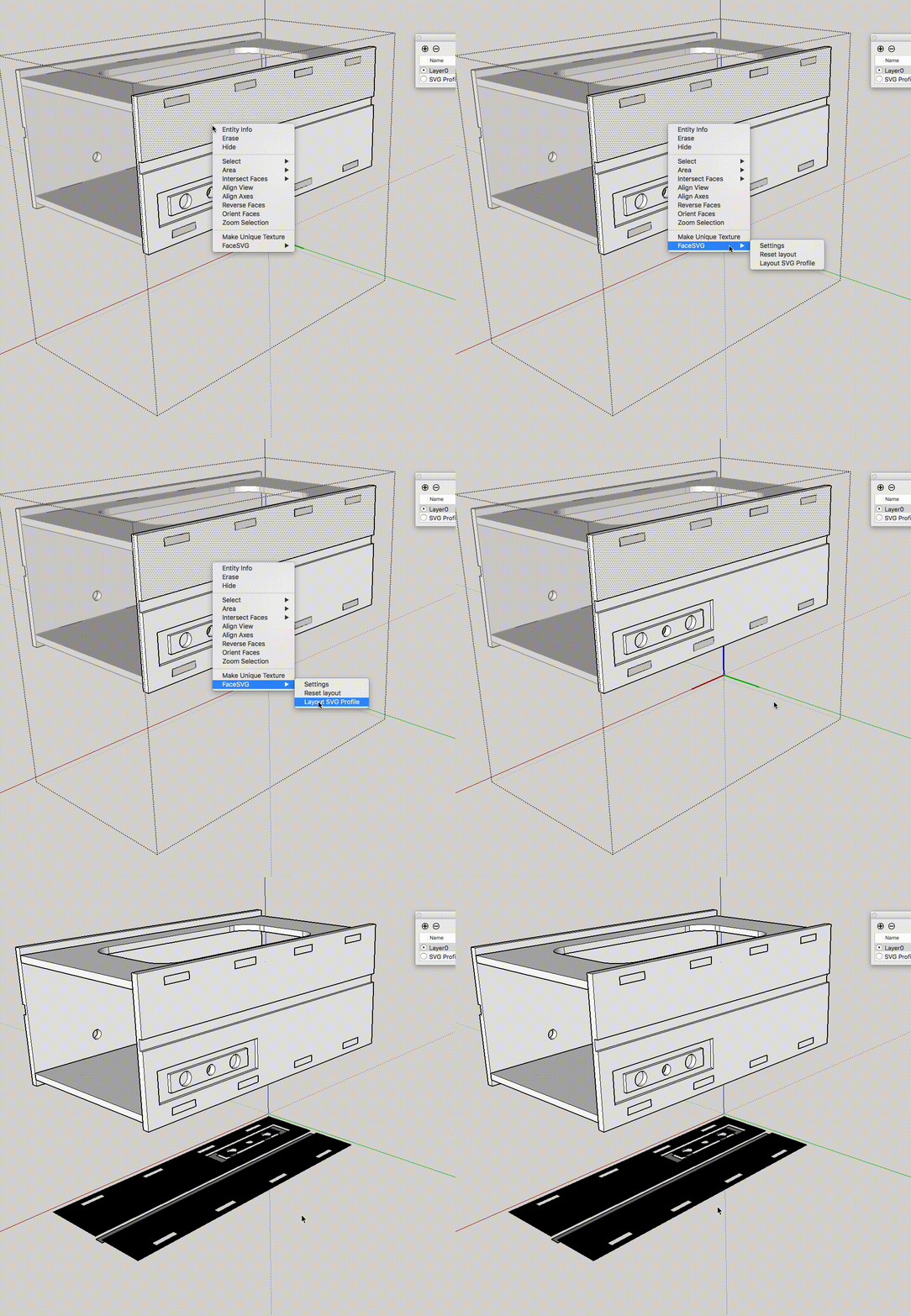
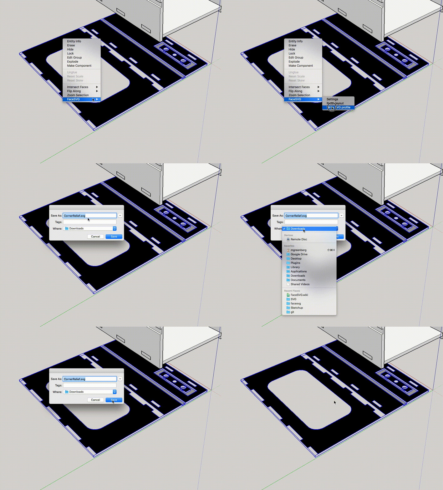
Once one or more faces have been generated into the SVG Profile Group, the FaceSVG context menu will include an operation to Write SVG Profiles. Selecting this will display a dialog to specify the location to write the SVG file.
To generate a mortise opening for a rectangular shape, cutting profile must include a radius to remove extra material at the corner. The FacseSVG plugin provides the capability to add these relief features to any desired rectangular openings. The desired approach for corner relief is set using the Settings menu, and is disabled by default.
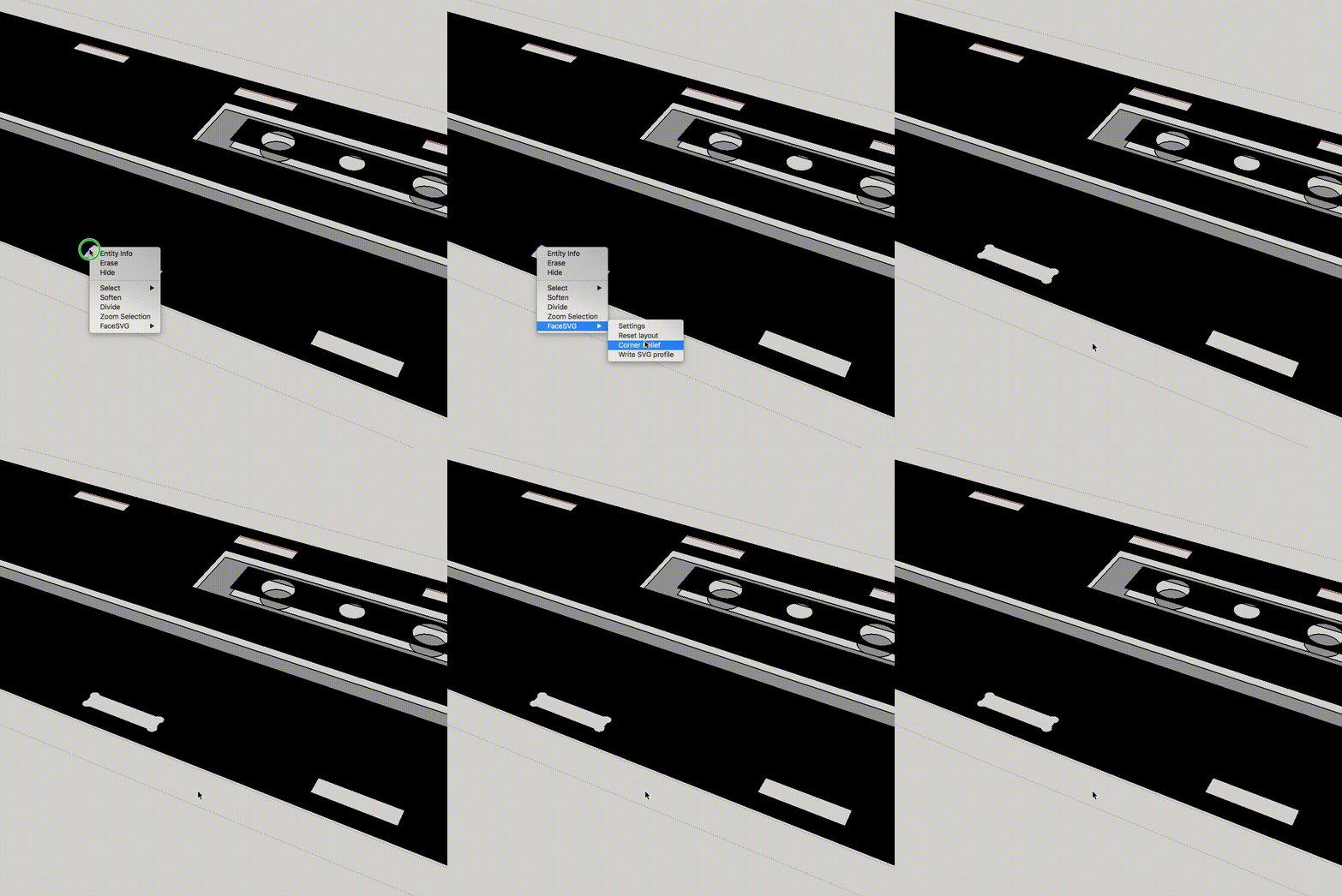
This is the approach where a radius is added to remove extra material at a 45 degree angle to each corner, symmetrically. For symmetric relief, any edge on a interior path rectangle may be selected. Selecting Corner Relief will then apply the modification to the selected rectangular opening.
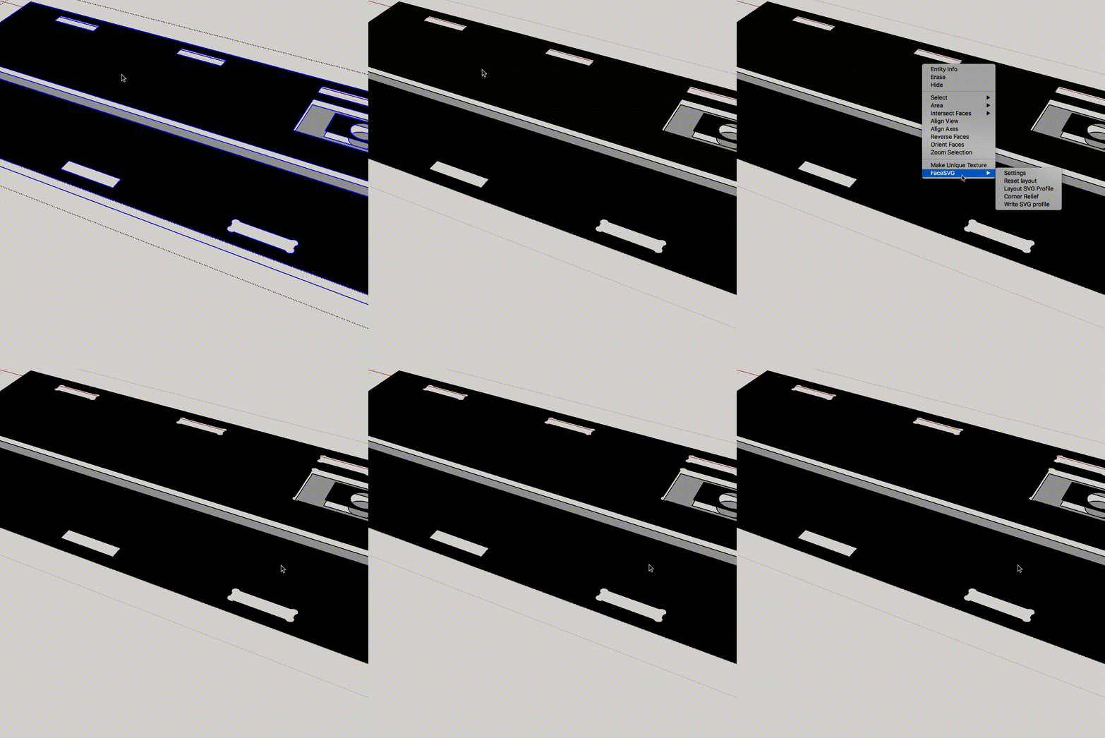
If it is desired to apply the same corner relief to all the openings in a face, the face can be selected.
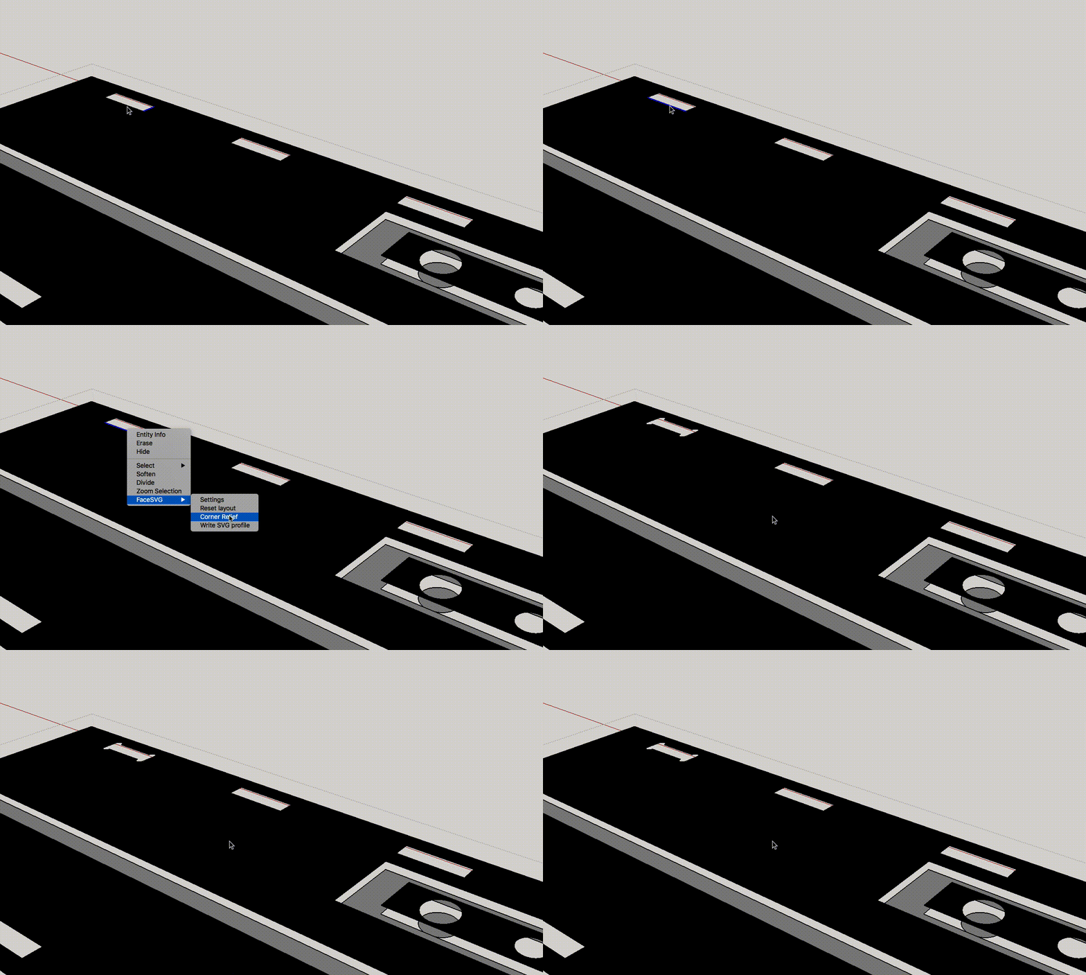
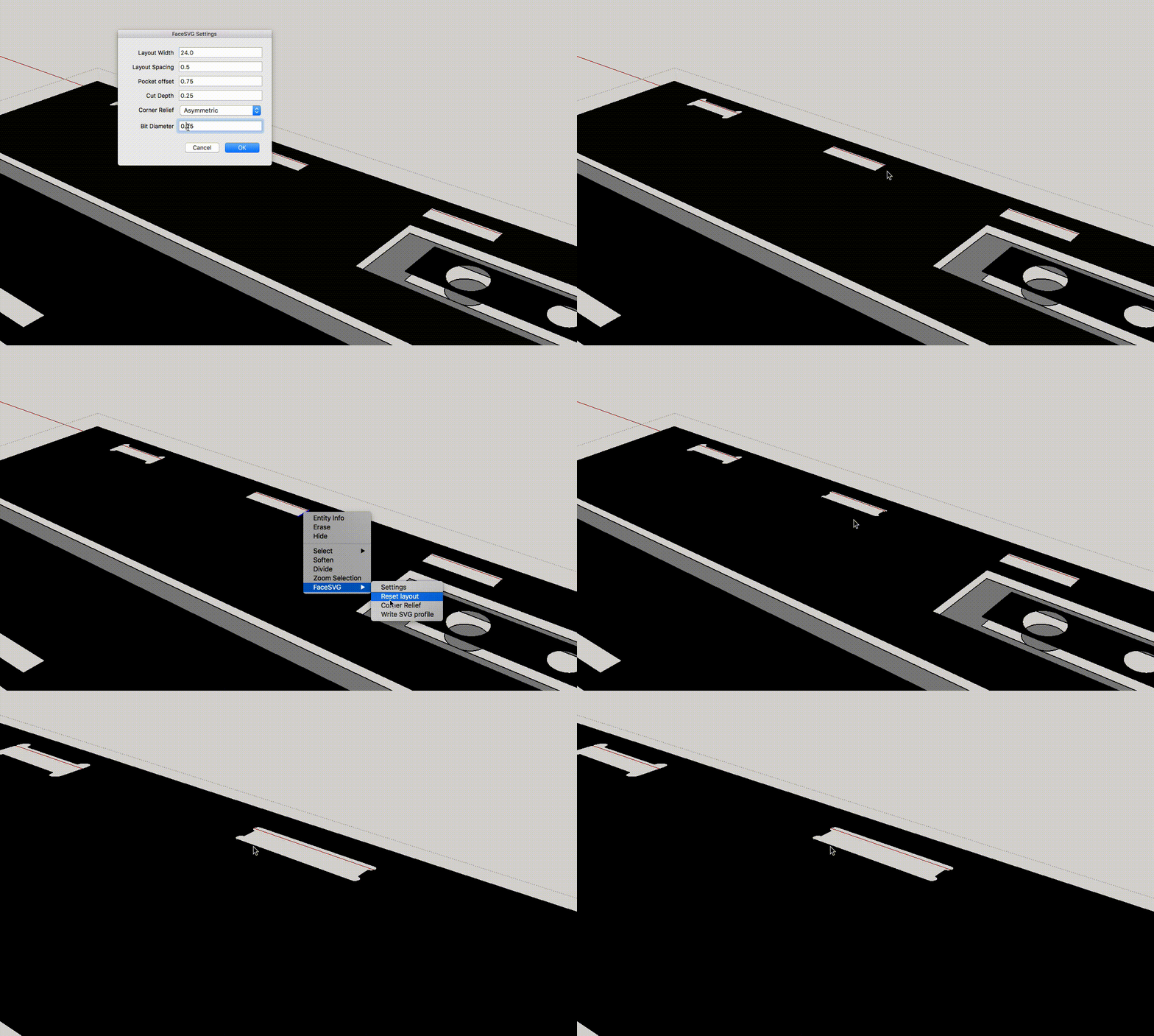
This is a little misnamed, but the idea is that the corner relief is only applied in one direction, to the opposite edges of the rectangle. When applying corner relief with this setting active, an edge is selected and the corner relief is applied to the selected edge and its opposite. As with the symmetric case, if the edge is not long enough the corner relief will not be applied.
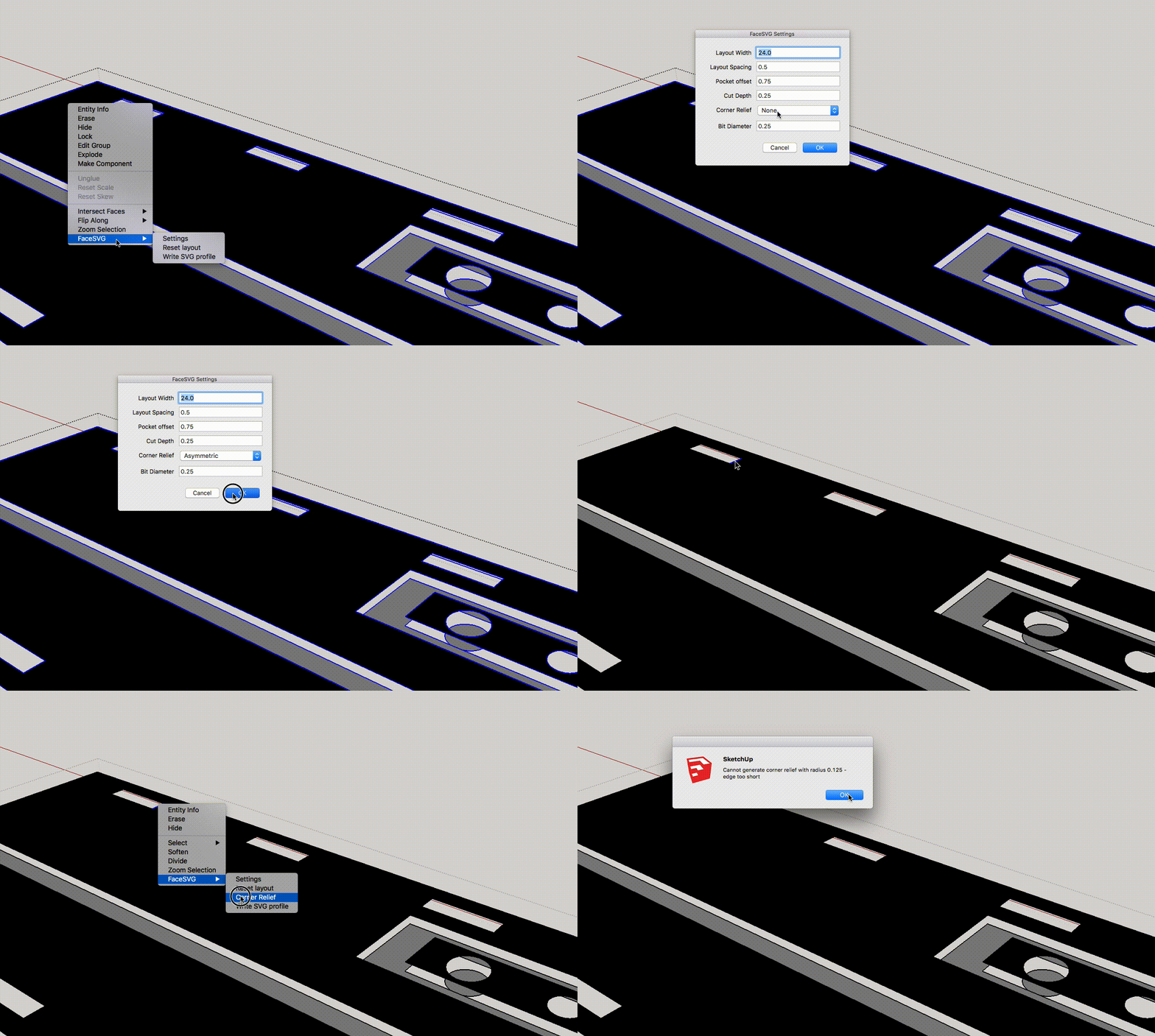
In this sample, simply selecting the longer edge will allow the corner relief to be applied.
Alternatively, using the Settings panel to enter a different bit size allows the corner relief to be applied to the smaller edge.
If Symmetric Relief, auto is enabled, corner relief will be automatically applied to the copied faces as each face is layed out into the SVG Profile Group. Only automatic symmetric relief is supported, since it is unambiguous how it should be applied. Usually, choosing asymmetric corner relief is more appropriate based on some detail of how the whole structure is assembled. For example, in the finished product some detail may cover one edge of the mortise opening, so putting the relief in that side is more aesthetically pleasing.
1 Currently the settings are not saved between Sketchup sessions. ↩