-
Notifications
You must be signed in to change notification settings - Fork 160
04. FreeIMU Calibration
Fabio Varesano the created of both the FreeIMU board and the library also developed a calibration GUI for IMU’s using his library and can be used for other IMUs codes as well. I am not going to recreate his description so here is a extract from his web pages (http://www.varesano.net/blog/fabio/freeimu-magnetometer-and-accelerometer-calibration-gui-alpha-version-out ):
-
FreeIMU Magnetometer and Accelerometer Calibration GUI. Currently, it should allow you to visually calibrate your accelerometer and magnetometer after you connected your IMU to a microcontroller running the FreeIMU_serial example in the FreeIMU library.
-
The program is written in Python, using PyQT4 as GUI library, using PySerial to communicate with Arduino, pyqtgraph for the graphs generation and PyOpenGL as backend for graph generation. Numpy and Scipi are instead used in the calibration algorithm.
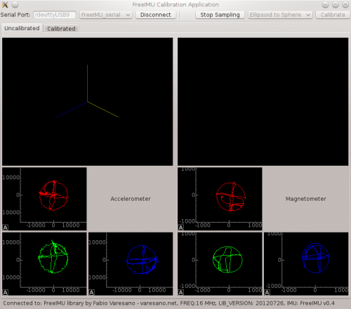
Here are a couple of pictures of the GUI..


In an article appearing in SENSORS article, Automatic Determination of Validity of Input Data Used in Ellipsoid Fitting MARG Calibration Algorithms (http://www.mdpi.com/1424-8220/13/9/11797), provides a nice review of the method and the importance of "properly distributed in space so data can be accurately fitted to the theoretical ellipsoid model". Suggest you read it. I will posted it in the documents section of the library.
jbesuchet developed a set of instructions over at Instructionables.com for his Gravity Touch Bluetooth project (http://www.instructables.com/id/Gravity-Touch-bluetooth-glove/step7/Testing-and-calibrating-the-FreeIMU/ ) which I will use a base for these instructions.
FreeIMU is an Open Hardware framework for orientation and motion sensing. The communication with the FreeIMU board is handled by the FreeIMU library for Arduino, Teensy and other Arduino compatible controllers. You can check out Fabio’s official website for additional information on the original library. Note only one change was made to his calibration code.
The official (no longer updated) FreeIMU GUI is in the repository (https://code.launchpad.net/~fabio-varesano/freeimu/trunk). If you would like to see the original version follow the steps below.
To download: Browse the code > view revision > download tarball
But it had calculation errors.
It is fixed by editing file n cal_lib.py:
From:
H = numpy.array([x, y, z, -y**2, -z**2, numpy.ones([len(x)], 1)])
to:
H = numpy.array([x, y, z, -y**2, -z**2, numpy.ones([len(x)])])
The official FreeIMU GUI used 115200 bad rate so remember to set the serial baud rate in the FreeIMU_serial example to 115200 or the program may hang when trying to connect. I have incorporated this change as well as setting up a option to let the GUI know whether you are a 32-bit (Due, Teensy 3.1) or a 16-bit (Mega 2560). Strongly suggest that you download the version in the FreeIMU Updates library.
As a note the calibration GUI is written in Python and is compatible with Python 2.7 (https://pypi.python.org/packages/any/p/pyserial/pyserial-2.7.win32.exe) so you will need to download this version (I have not tried it with later versions). There are several dependencies that you need to be aware of
-
PyQT4
-
PySerial
(https://pypi.python.org/packages/any/p/pyserial/pyserial-2.7.win32.exe)
-
Numpy
(http://jaist.dl.sourceforge.net/project/numpy/NumPy/1.9.1/numpy-1.9.1-win32-superpack-python2.7.exe)
-
Scipy
-
PyQtGraph
(http://www.pyqtgraph.org/downloads/pyqtgraph-0.9.8.win32.exe)
-
PyOpenGL
(https://pypi.python.org/packages/any/P/PyOpenGL/PyOpenGL-3.1.0.win32.exe#md5=f175505f4f9e21c8c5c6adc794296d81) Make sure you use either totally 32-bit or totally 64-bit versions.
A great site to download Python Packages and Python is Christoph Gohlke Unofficial Windows Binaries for Python Extension Packages at http://www.lfd.uci.edu/~gohlke/pythonlibs/.
Here is the step to be up and running:
-
Download the FreeIMU-Update library.
-
Setup your Arduino environment as explained in the Additional Arduino Libraries section of Arduino's documentation.
-
Copy the FreeIMU_GUI directory to any location on your computer just remember where so you can go back to it when you want
-
The result of the calibration process will be a file: "calibration.h" needed to obtain stable orientation measurement from the FreeIMU.
Once you have downloaded the library, follow the Additional Arduino Libraries guide to setup your Arduino environment. Choose the manual installation so that you will have a better understanding of the folder structure of the Arduino environment.
Note: You will need to use** Arduino 1.5.7 **for Arduino boards and 1.05r2 with Teensyduino installed if you want to use it with a Teensy board.
-
Connect the Arduino to your computer.
-
Launch the Arduino Editor program and open the "FreeIMU serial" sketch under "File -> Examples -> FreeIMU -> FreeIMU_serial" if you are using a Arduino or the “FreeIMU_ FreeIMU_serial_ARM_CPU” if you are using one of the ARM based CPU.
-
Select your board under Tools -> Board.
-
Select the serial port on which the Arduino is connected (Tools -> Serial Port) and write down the name of the port (Windows something like COM2, Mac something like /dev/tty.usbmodem1421).
-
Upload the sketch
-
To make a quick test to check that the Arduino responds, open the Serial Monitor (Tools -> Serial Monitor), check that the properties of the communication are "Newline" and "57600 Baud". Put “v” in the input field and press "Send" button. If everything is ok, the Arduino will send you back:
FreeIMU library by Fabio Varesano - varesano.net, FREQ:16 MHz, LIB_VERSION: DEV, IMU: FreeIMU v0.4 NOTE: there may be a delay until the MPU resets – do not move the IMU if are using the Invensene MPUs.
-
You can play with others commands to see the response of the Arduino, here is the current list “1’ = Reset the IMU
“2” = Zero the Quaternion Matrix “g” = Zero Gyros “t” = implement temperature compensation “f” = turn off temperature compensation “pxxxxx” = input sea level reference pressure in milibars*100, i.e. p101325 for 1013.25 mb which is the default if you do not input anything “r” = outputs raw values of the sensors Ax, Ay, Ax, Gx, Gy, Gz, Mx, My, Mz, ??, pressure, temp (if you have a pressure sensor attached), time in milliseconds “b” = outputs raw accelerometer and magnetometer data for the calibration GUI “q” = outputs quaternions “z” = outputs all calibrated and calculated values for use in the processing sketch Gx, Gy, Gz, Ax, Ay, Az, Mx, My, Mz, q0, q1, q2, q3, MPU temp, heading, pressure, atms temp or sensor temp if no pressure sensor, 10 values of GPS data if selected “a” = same as “z” except a 1d Kalman filter is applied to the accelerometer readings. “c” = write calibration data to the Arduino Uno EEPROM (used with the GUI) “x” = reload calibration “C” = lists the calibration data “d” = debugging data output -
The application that comes along with the FreeIMU library to test if your FreeIMU is working properly is "FreeIMU_cube_Odo.pde". This is a Processing sketch, so you will need to download Processing version 2.0b7 to run it. The GUI of processing is really similar to the Arduino Editor. Open " FreeIMU_cube_Odo.pde " with processing, it is located under: " /processing/FreeIMU_cube/FreeIMU_cube_ODO.pde". Suggest that you use the latest version in the Experimental folder.
We need to tell the program on which port the Arduino is attached to. To do so find the code written below in the Processing's code:
final String serialPort = "xxxxxxxxxxxxxxx"; // replace this with your serial port. On windows you will need something like "COM1". XXXXXX is variable depending on port. Currently defaults to a com port also
myPort = new Serial(this, serialPort, 57600); //change baudrate to match the FreeIMU.ino sketch baudrate selected
Replace "/dev/ttyUSB9" by the serial port name you wrote down before (the port name the Arduino is attached to).
-
Run the program, if everything goes well you should see a Window with a 3D cube on it. The cube represent your FreeIMU so when you move your FreeIMU, the cube should follow the mouvement. If it is not the case, don't panic! We must calibrate the FreeIMU.
-
If you get some errors or if the program doesn't start (just a void window), try to reset your Arduino and relaunch the program. If it doesn't work please check the troubleshooting section on the FreeIMU website. Alternately, would suggest that you use “FreeIMU_cube_Odo_Exp_v2.pde” in the “experimental/processing directory”. Better visualization and additional options which we will get into later.
-
Assuming you have installed Python 2.7 and the additional packages identified earlier, go into the FreeIMU_GUI directory.
-
There are two variables that you will need to set prior to using the calibration GUI:
The first is a workaround for 16-bit (Arduino Uno, Mega 2560, etc.) versus 32-bit (Arduino Due, Teensy 3.1, etc.) CPUs.


Open the cal_gui.py with an editor of your choice, I use primarily IDLE that comes with Pyhon or Notepad++ . IDLE has the advantages that once you make the change you can run the GUI right from IDLE. The following instructions use IDLE.


Typically, I will right click on cal_gui.py and select edit with IDLE from the Windows context menu.
Find the following lines in the code (line 40):
  `#####`


  `##`


  `## For 16-bit processors use word = 2`


  `## For 32-bit processors use word = 4`


  `##`


  `#####`


  `word = 4`


  Change word to either 2 or 4 per the instructions


  The second is the baudrate (line 168). Find the following line in the code:

    baudrate=57600,


  Change the 57600 to match the FreeIMU serial sketch baud you selected. Currently the GITHUB library has 57600 as the default baud since I am also testing with transmitting the data over an XBEE.
-
Hit the F5 key and the calibration GUI will start up – usually takes a few seconds to start so be patient.
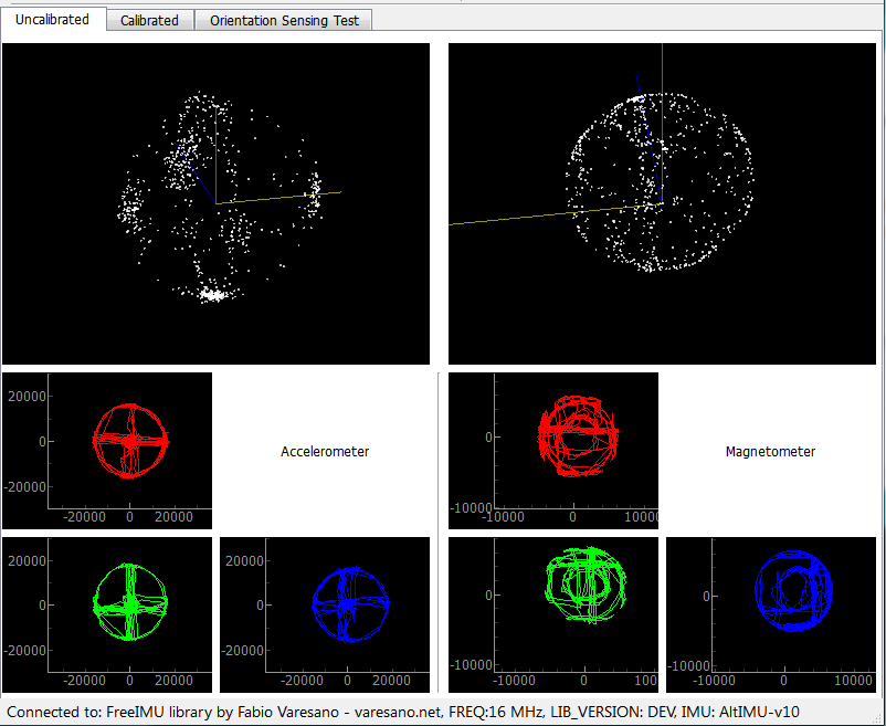
Once it starts you will see the following screen:

To use:
  1.Type the com port for the Arduino in the “Serial Port” box


  2.Click “Connect”


  3.Once connected click on “Start Sampling”. This will start the GUI sending requests for data from the FreeIMU_serial sketch that you loaded previously.


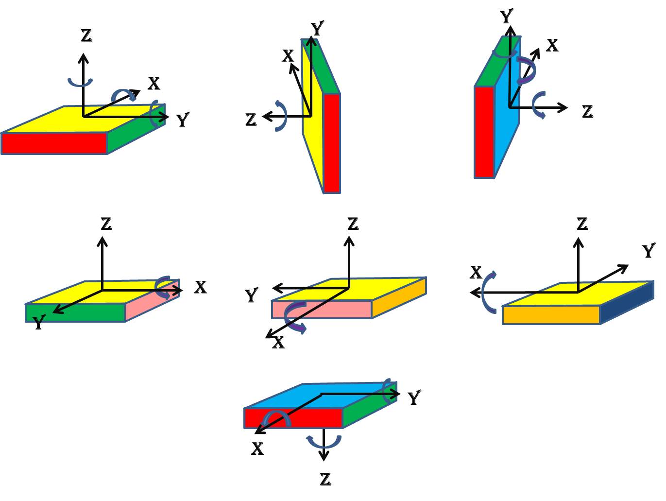
  4.I have had the most luck with calibrations that follow the rotation scheme.  Just remember to rotate the board slowly and steadily around the axes:

-
  NOTE: Once you start sampling you can put the cursor in anyone of windows and drag the frame around until you center the data points in the window. Also, if you use the scroll wheel on your mouse you can zoom in or out.  Helpful when the data isn’t centered around 0, 0 which it won’t be.


The idea is to collect enough data to fully define the sphere/ellipsoid which is done by rotations around all the axes.


Recommend that you check out the following Youtube videos:

* Adafruit 10 DOF IMU Calibration with FreeIMU GUI Toolset
* our freeimu 0.4.3 calibration procedure
* Automated FreeIMU (MPU-6050) Calibration
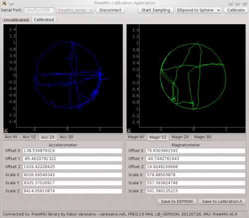
Once you are satisfied with your data click on “Stop Sampling” and you should see something like this:

Then click the “Calibrate” button. This will bring you to the screen with the calibration values for the accelerometer and magnetometer. If you select the Accel 3D and Magn 3d tabs on the calibration screen you should wind up seeing something like the below figure:

One last step and you will have your calibration finished. Click on “Save to calibration.h”, select the folder you want to save the calibration file (libraries->FreIMU->calibration.h), and then save it. That’s it for calibration.
Reload the FreeIMU sketch. That’s it. Re-test with the Free_cube_ODO processing sketch.
Additional notes from Fabio’s website that you might find interesting during your calibration process:
Hi Manor, thanks for sharing Submitted by fabio on Thu, 2012-11-15 09:31. Hi Manor, thanks for sharing your video. However, this is still not a proper calibration approach.
You are not making a circle on the acc XY plane and you are not making the biggest circles on the magnetometer. Both these are crucial to get better results.
This is what you have in your XY plane for the accelerometer:

This is wrong. You did not made complete circle on this one. The green line is what it should look like for proper calibration.

This is what you have for the XY plane for the magnetomter. This is also wrong.. See those areas marked in red by myself? These are synthoms of the fact that you didn't make the biggest circle possible... the green line shows you how this should look like.
Rotation XY plane Submitted by Sjef (not verified) on Thu, 2012-11-15 09:45.
Hello Manor,
In addition to what Fabio said:
You have to rotate around the 4 sides of the box too.
In a way that each side of the box has touched the "ground".
You get the biggest circle in the XY plane when you do this.
The last movement you did in the video (movement of rotating the bottom of the IMU box on the "ground") isn't necesarry.
Hope this helps,


