-
-
Notifications
You must be signed in to change notification settings - Fork 372
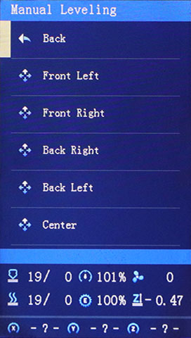
Bed tramming menu
Bed tramming menu, allows to level the corners to get nozzle (X) and bed (Y) have parallels movements to each other.

In the Manual mesh version, the nozzle moves over each corner position and then goes down to z=0, you can use a piece of paper to adjust the knobs.
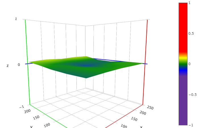
In the BLTouch version the corners leveling is semi-assisted, the printer does a z-home and moves the BLTouch over the leveling point then does a metering taking the distance between the corner and Z=0, the result of this relative height is showed in the status line. You can adjust the leveling knobs until the values are similar in the four corners, they don't need to be zero because when the bed is warped (most of them are concave/convex, see Fig 1), the corners are always higher/lower than the center z=0, which is taken as reference. A slight difference between the corner heights of about 0,05 mm is enough. If you try to get zero in the corners, the next time Z is homed you will see again non zero values because of the relative heights of the corners are maintained.
Fig 1. Warped bed as seen with the Octoprint plugin Bed visualizer.

If your printer has a CR/3D/BLTouch the Bed Tramming Wizard will be enabled, it can help you with the tramming procedure. The relative heights of all corners are compared with the average and the wizard will suggest to you what corner must be raised/lowered. The hardcoded tolerance for the difference between the highest corner and the lowest corner is 0.05 mm. If you run a bed tramming again and Z is homing you could get different values, that is not a bug because the bed tramming wizard uses the average values. Please don't confuse the bed tramming wizard values with mesh leveling values, they are different systems with different ways of calculating data.


If your BLTouch doesn't go to some points, you have unreachable points because your mesh insets, probe/home offsets and/or physical dimensions. For example, the X probing points are reachable positions if:
Probe X position> MAX( X MIN position (0) + Probe X Offset (-42), Mesh MIN X (25) )
Probe X position< MIN( X MAX position (248) + Probe X Offset (-42), Mesh Max X (205) )
Numbers in () are only examples of the default Ender 3V2 physical settings.
If you continue to have a problematic test, disable the HS mode or decrease the probe z-feed rate, and review your BLTouch wire connections. If nothing helps then your BLTouch could be incompatible with this firmware or the standard connectivity, some users have success re-routing the sensor wires to the z-end stop connector and recompiling the firmware for that connection.
It is not necessary that the probe or nozzle goes exactly over the knob screws, that only has sense during the Assisted Tramming (G35), in more accuracy printers, where the screw thread type is known and you have the possibility to follow the indications for turn the leveling screws in degrees and minutes.
This Wiki and the included images were created under the Creative Commons License CC BY-NC-SA
Get the latest firmware here: https://github.com/mriscoc/Ender3V2S1/releases/latest