-
-
Notifications
You must be signed in to change notification settings - Fork 10.3k
New issue
Have a question about this project? Sign up for a free GitHub account to open an issue and contact its maintainers and the community.
By clicking “Sign up for GitHub”, you agree to our terms of service and privacy statement. We’ll occasionally send you account related emails.
Already on GitHub? Sign in to your account
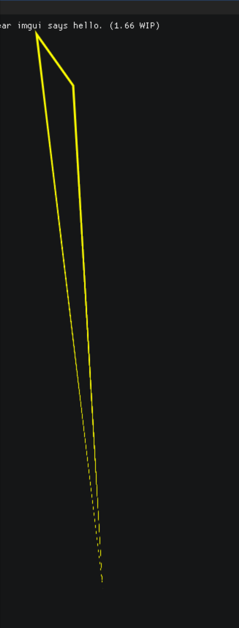
Bug in drawing thick antialiased polylines #2183
Comments
|
Has anyone addressed this issue/any workarounds? My application heavily depends on this feature and I might just look at nanovg or something for a custom implementation. |
|
Maybe @rmitton would have a suggestion? |
|
The current line-drawing algorithm does not handle thick-edged lines correctly, it never has.
I made a small modification that fixes it for obtuse angles (the most common ones in UI) but acute angles like this one still suffer.
We need a new line algorithm that knows how to insert extra cap vertices around the corner so that we can handle acute angles too.
|
|
As it stands out, I only need straight lines for my application, hence using anti-aliased lines is a waste of resources for me. I edited the non anti-aliased portion of |
|
Would your patch make sense as a PR ? May be useful as a reference even if not covering all cases. Otherwise the lesser evil if to copy |
|
Sorry for the late reply, I was caught up with some stuff. I'll post the snippet here as a reference for those who might need it. |
|
Continuing #2868 here Possible fix with no additional sqrt, place here: Line 701 in 3c238ec
for (int i1 = 0; i1 < count; i1++)
{
    const int i2 = (i1+1) == points_count ? 0 : i1+1;
    unsigned int idx2 = (i1+1) == points_count ? _VtxCurrentIdx : idx1+4;

    // Average normals
    float dm_x = (temp_normals[i1].x + temp_normals[i2].x) * 0.5f;
    float dm_y = (temp_normals[i1].y + temp_normals[i2].y) * 0.5f;

    // direction of 1st edge
    float v0x = -temp_normals[i1].y;
    float v0y = temp_normals[i1].x;

    // project direction of 1st edge on 2nd edge normal
    float dot = v0x * temp_normals[i2].x + v0y * temp_normals[i2].y;

    // -direction of 2nd edge
    float v1x = temp_normals[i2].y;
    float v1y = -temp_normals[i2].x;

    // scale
    dm_x = (v0x + v1x) / dot;
    dm_y = (v0y + v1y) / dot;

    //IM_FIXNORMAL2F(dm_x, dm_y);
    float dm_out_x = dm_x * (half_inner_thickness + AA_SIZE);
    float dm_out_y = dm_y * (half_inner_thickness + AA_SIZE);
    float dm_in_x = dm_x * half_inner_thickness;
    float dm_in_y = dm_y * half_inner_thickness;

    // Add temporary vertexes
    ImVec2* out_vtx = &temp_points[i2*4];
out_vtx[0].x = poin |
|
@nem0 That code does seem to fix the mitre issue, but misses off the final segment of the line. See the picture below: I'll have a look and see if I can fix it. |
|
I feel like there's a better way to do it (the math goes a bit over my head here) but I made it work: for (int i1 = 0; i1 < count; i1++)
{
const int i2 = (i1+1) == points_count ? 0 : i1+1;
unsigned int idx2 = (i1+1) == points_count ? _VtxCurrentIdx : idx1+4;
// Average normals
float dm_x = (temp_normals[i1].x + temp_normals[i2].x) * 0.5f;
float dm_y = (temp_normals[i1].y + temp_normals[i2].y) * 0.5f;
// Direction of 1st edge
float v0x = -temp_normals[i1].y;
float v0y = temp_normals[i1].x;
// Project direction of first edge on second edge normal
if (closed || i2 != count)
{
float dot = v0x * temp_normals[i2].x + v0y * temp_normals[i2].y;
// Negative direction of 2nd edge
float v1x = temp_normals[i2].y;
float v1y = -temp_normals[i2].x;
// Scale
dm_x = (v0x + v1x) / dot;
dm_y = (v0y + v1y) / dot;
}
else
{
IM_FIXNORMAL2F(dm_x, dm_y);
}As you can see from the big spike at the bottom of the graph, sometimes the generated mitre is very big, but that's a necessary part of the algorithm, I guess. Rounded corners would need too many polygons, I presume. @ocornut, I can make a PR if you'd like. |
|
@Omegastick I checked only closed polylines. To fix the nonclosed polylines, add: if (!closed && i1 == count - 1) {
dm_x = temp_normals[i2].x;
dm_y = temp_normals[i2].y;
}
before float dm_out_x = dm_x * (half_inner_thickness + AA_SIZE); |
|
A bug was fixed today, see my post @martincohen : the bug fix unfortunately doesn't fix the exact issue outlined in your initial post (it should look exactly as your screenshot above, note that before today's fix it looked worse), but as the post was made just before another bug was introduced and most discussions happened after that bug was introduced, things got confusing. However while fixing I've understood the how raising our scaling limit essentially "fixes" your triangle (in concrete term raising the @nem0 @Omegastick Without the scaling limit: (notice the red circle is the provided point) (
TL;DR; need some kind of miter (opt-in and configurable) |


Version/Branch of Dear ImGui:
dear imgui, v1.66 WIPBack-end file/Renderer/OS: (or specify if you are using a custom engine back-end)
Back-ends: imgui_impl_dx11.cpp + maybe others (haven't tested, but I expect the bug be in the imgui_draw.cpp)
OS: Windows 10
My Issue/Question: (please provide context)
Best described with image:

Without AA it seems to work as one would expect. Both thick lines (thickness > 1) and thin lines (thickness <= 1) are affected, also closed/not closed flag doesn't seem to have effect on this.
The text was updated successfully, but these errors were encountered: