CC1101
To use the CC1101 in Bruce, turn off your M5 device and connect the module following the pinouts listed in this page.
Turn on the device, then navigate to "RF->Config->RF Module" and select "CC1101 on SPI" (pics here).
If the "CC1101 not found" error message appears, turn off the M5 device, recheck the wiring and try again.
If no error is shown, then the CC1101 is initted correctly, and you can use it in the RF menu.
For this module you can also set a custom frequency in the supported subranges: 300-348 MHZ, 387-464 MHZ and 779-928 MHZ. Setting an empty or invalid frequency will reset to the default 433.92 MHZ. This setting will only affect the receive and jamming features. Transmitting from a sub file will always use the frequency specified inside the file regardless of the user setting.
Same pinouts used in this project, watch the tutorial here:

- GDO0_PIN=25
- SS_PIN=26 ; chip select. wrongly labelled as "CKN" in some boards
- MOSI_PIN=32
- SCK_PIN=0
- MISO_PIN=33
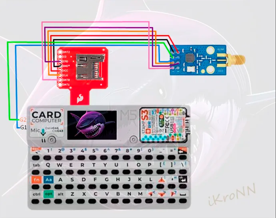
Combined connection with an SD card module is still WIP, subscribe this issue for updates: https://github.com/pr3y/Bruce/issues/249
This requires a microSD sniffer (shared with the SD card) and some soldering skills.
| Pin | CC1101 | SD Sniffer | Cardputer |
|---|---|---|---|
| 1 | GND | GND | |
| 2 | 3,3V | Vcc | |
| 3 | GDO0 | Grove SDA (2) | |
| 4 | CSN | Grove SCL (1) | |
| 5 | SCK | CLK | |
| 6 | Mosi | CMD | |
| 7 | Miso | DAT0 | |
| 8 |
OR you can try your soldering skills and use this pinouts:
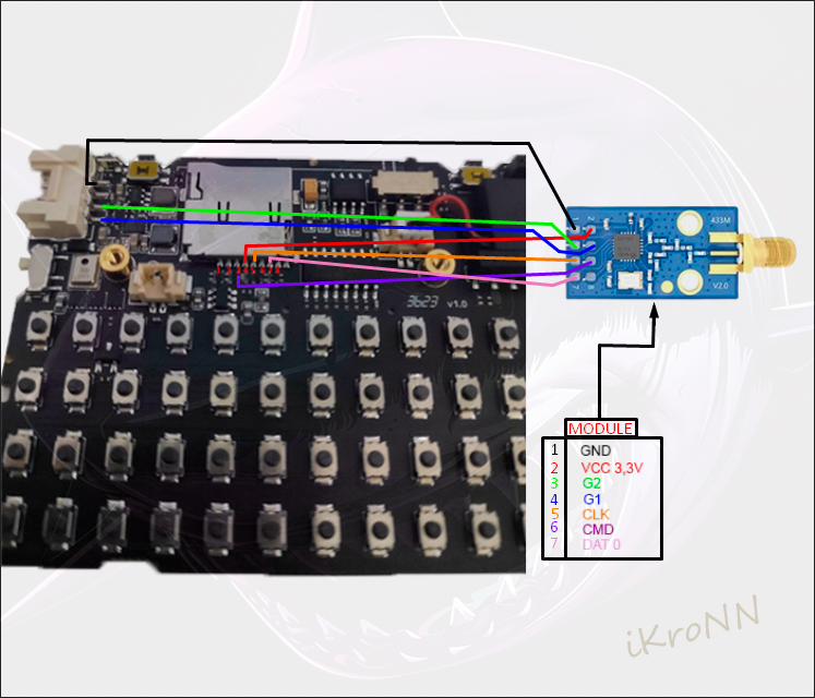
Pinouts discovered by @PAZGUSTAVO, thank you!
Works with the microSD sniffer:
- GDO0 PIN = 22
- CSN/SS PIN = 27

Schematics thanks to @C.Oliveira