Home
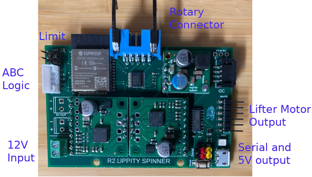
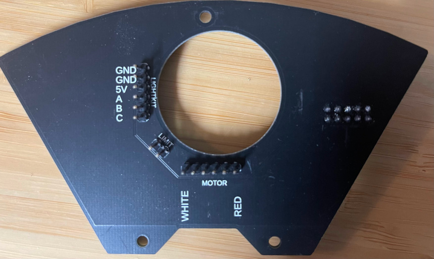
- ABC Logic is 5 pins. Starting from the top: Ground - A - B - C - Ground
- Serial header can only receive. There are two headers to allow you to daisy chain devices.
- Do NOT supply 5V to the board. Power should only be applied to the board via the 12V terminal or the USB connector. The Uppity board can supply 5V 5A to other boards. Two extra screw terminals are provided should you wish to use them.
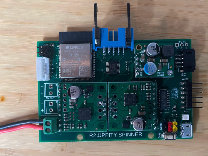
- Secure your 12V supply wire using the screw terminal. Not powered.
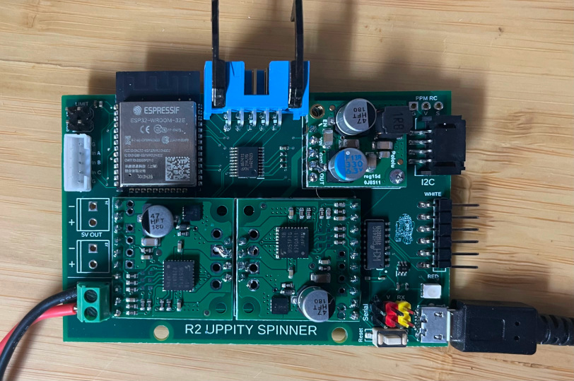
- Connect the USB cable to the board. Leave the other end of the USB cable disconnected.
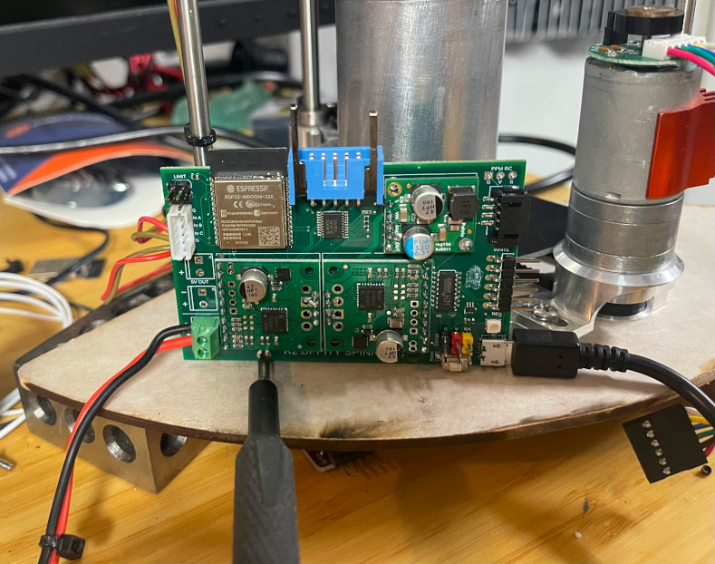
- Using one screw gently tighten the board so that it stands straight. Do NOT over tighten the screw. The USB cable can torque the board and break some solder joints.
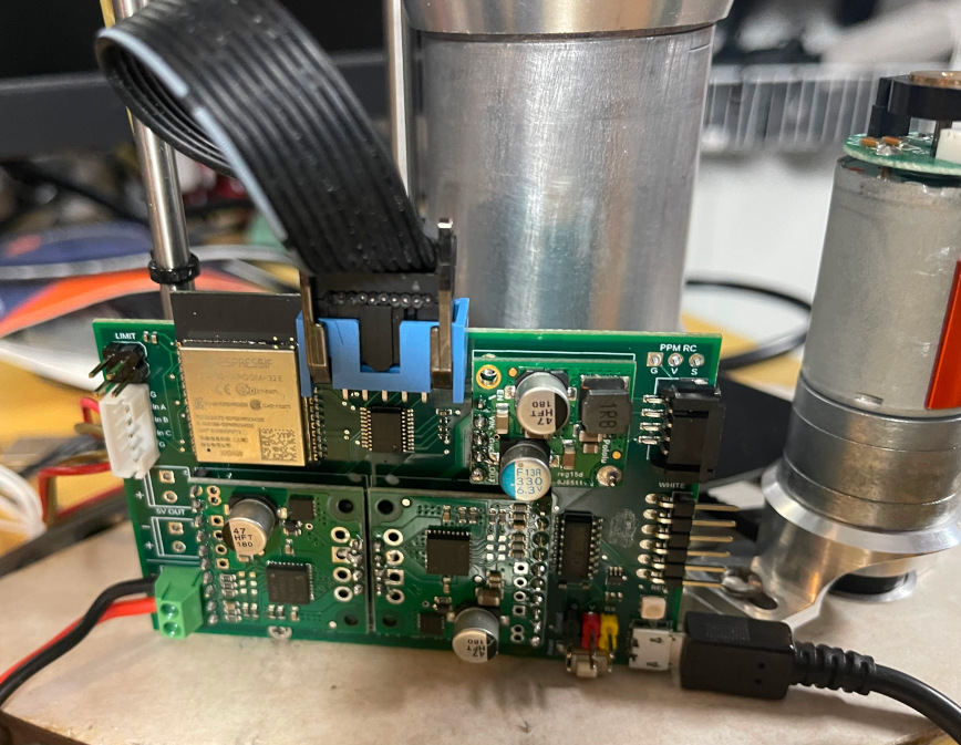
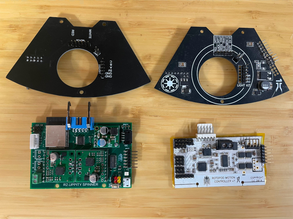
- Connect the ribbon cable
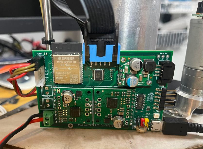
- Connect the top/bottom limit switches
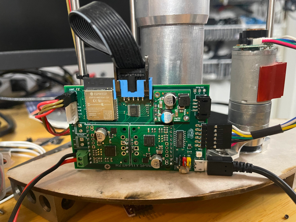
- Connect the lifter motor as marked on the board. White wire on top. Red wire on bottom.
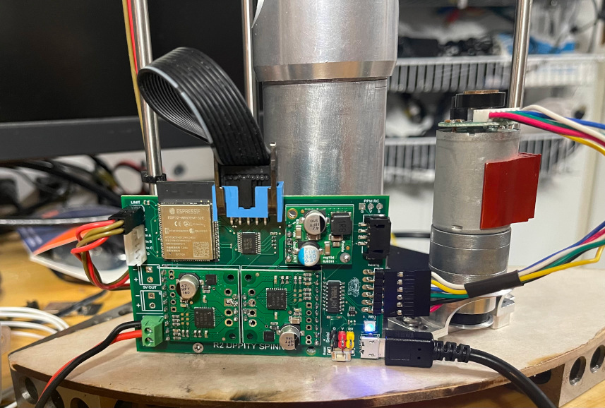
- Connect the other end of the USB cable to your computer and connect your 12V supply.

- Open a Serial Terminal on your computer and connect at 115200 baud to the board.
- Type #PSC and hit Enter
- If the board responds with Invalid. Try again.


- Now you should be able to send it commands like :PS0
- For full list of commands check-out https://github.com/reeltwo/R2UppitySpinnerV3