Divergence when using fluid interface #1414
Description
Summary
The fluid interface connects RANS zones in such a way that flow can freely pass through it just as if they were a single RANS zone. We (@maxaehle, @BeckettZhou) observed convergence problems in cases where the meshes had "boundary-layer-like" high anisotropy at the fluid interface. However a singlezone simulation, for which the meshes are joined together, converged.
Setup (.cfg, .su2)
Density for singlezone run with joined meshes, converged:
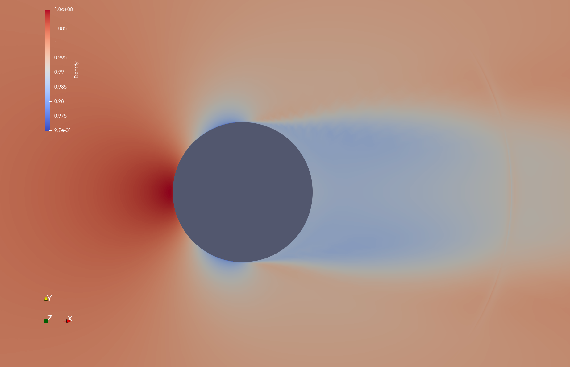
Density for multizone run with separate meshes and fluid interface, diverged:
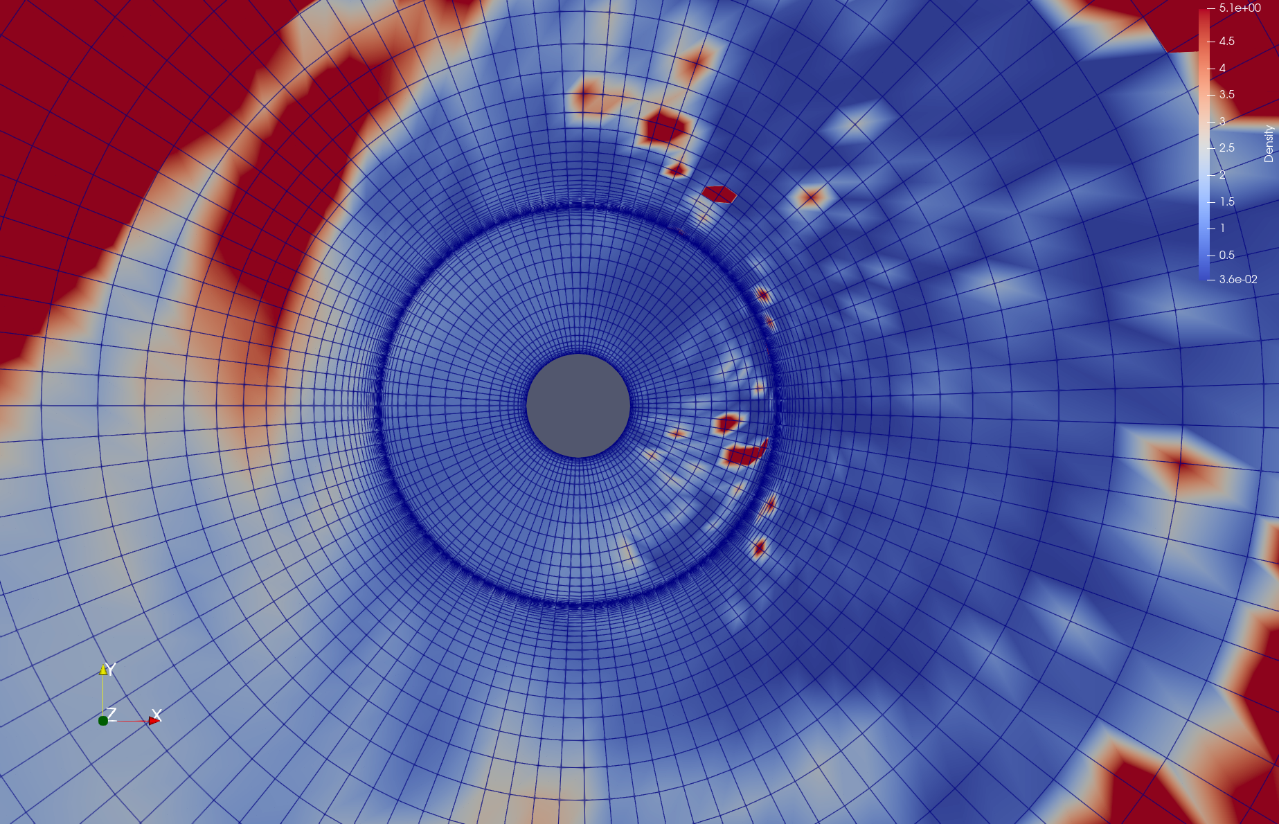
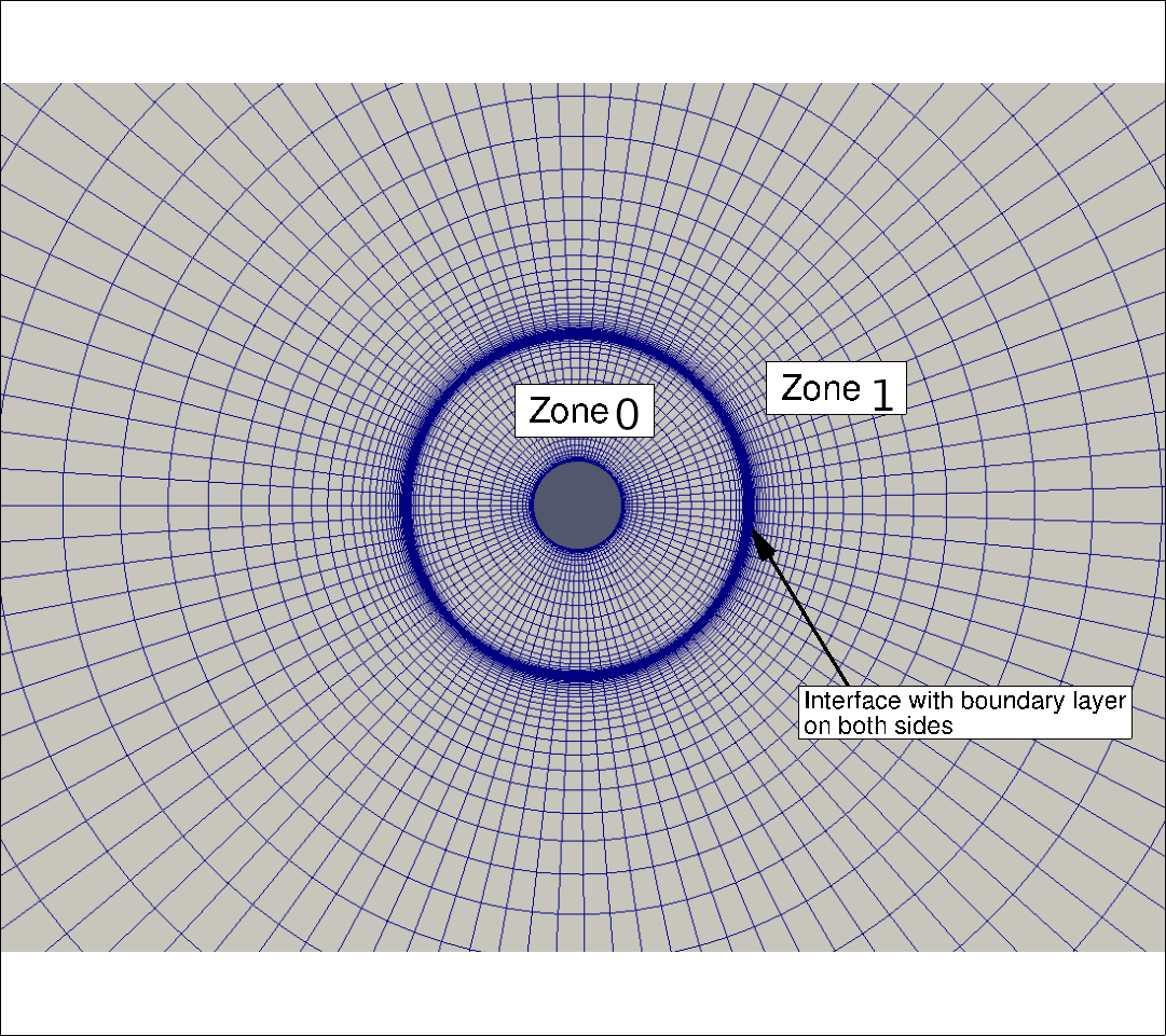
Mesh:
Download link: https://seafile.rlp.net/d/bb0fbb16eb414263b642/
In this issue I consider compressible flow around a circle at Re=1e6, Mach=0.15, using the SST turbulence model. The radial mesh has a boundary layer at the circle of radius 1 (adiabatic wall), and a "boundary-layer-like" structure around a circle of radius (approximately) 4. Having this "boundary-layer-like" structure does not make sense here, but in our project we later want to change the area 1<=radius<=4 to a "porous material" zone and this would introduce a boundary layer there.
Both the attached issue_complicated.zip, issue_simplified.zip contain subdirectories singlezone, multizone. I observed the problem best for issue_complicated.zip. With issue_simplified.zip I try to provide a minimal working example, and it reproduces the same convergence/divergence behaviour, but I'm not sure whether it really covers the complete problem. issue_simplified.zip has been created as follows:
- In the singlezone setup, the whole mesh has been exported to
singlezone.su2. Thesinglezone.cfgisTestCases/rans/naca0012/turb_NACA0012_sst.cfgwith adapted mesh filename, marker names and Reynolds number, andRESTART_SOL=NO. - In the multizone setup, the mesh has been split into two zones.
multizone-0.su2is the inner "ring" of1 <= radius <= 4between the circle and the "boundary-layer-like" structure.multizone-1.su2is the remaining part4 <= radius. I created amultizone.cfgthat refers tomultizone-0.cfg,multizone-1.cfgand joins the zones by aMARKER_FLUID_INTERFACE. The twomultizone-i.cfgs are identical to thesinglezone.cfgexcept that the mesh filename and markers we adapted again, and theITER=option was removed.
In issue_complicated.zip, filenames and cfg files are a bit different but the meshes are the same.
Observed and expected behaviour
I would expect that the two simulations give similar results. However, the singlezone setup converges while the multizone setup diverges (SU2 has diverged (NaN detected). or SU2 has diverged (Residual > 10^20 detected).). The same behaviour is observed for CFL=10 instead of 1000, and also for SA with CFL=10. I ran v7.2.0 (commit 3ec1c68) in serial (without MPI).
I reported a similar problem some time ago in the developer meeting, with a "chopped NACA 0012 airfoil" testcase. For this issue we created this more basic example which seems to reproduce the error (although I am not completely sure). Typically we would see the SU2 has diverged (Residual > 10^20 detected). error.
Differences between multizone/fluid-interface and singlezone/joined-meshes
We came up with the following differences:
-
Flux calculation across the interface: The flux between neighbor cells
i,j, one of which hasradius<4and the other one hasradius>4, is computed differently.-
In singlezone this is just an ordinary flux computation along an edge
i-j, withCSolver::Upwind_Residual(,Viscous_Residual). -
In multizone this flux between two zones is computed by
CSolver::BC_Fluid_Interface. When the method is called to compute the contribution of the interface on the residual of contol volumei,thisis the solver object of the zone of control volumei, so we can access all variables ati(like primitive, turbulent, and their spatial gradients) and give them to theCNumericsobjects. However we cannot access the variables atjdirectly! Through the "interface" mechanism, we get values of the primitive and turbulent variables atj, but not their gradients. That's why theBC_Fluid_Interfacehas lines like this:visc_numerics->SetPrimVarGradient(nodes->GetGradient_Primitive(iPoint), nodes->GetGradient_Primitive(iPoint));
I tried to fix this by transferring gradient information also, but it did not solve the problem.
-
-
Calculation of spatial gradients: Both in the Green-Gauß and the Weighted-Least-Squares calculation, in order to compute the gradient of a quantity
xat a pointionly the values ofxati, and neighbors ofiin the same zone, are taken into account. This means that the gradient at points withradius==4is based on less information, and hence is more inaccurate, in the multizone setup. -
General structure of the drivers: Maybe there are relevant differences between
CSinglezoneDriverandCMultizoneDriver, I don't know.