-
Notifications
You must be signed in to change notification settings - Fork 5
TransitNetworkCoding
Home > TravelModel > UsersGuide > NetworkCoding > TransitNetworkCoding
The transit network consists of the following types of files:
The transit network is created from these files plus the transit background network that is created from the highway network. Before describing the files, it is important to introduce the transit modes and provide an example of transit network coding.
The MTC transit network consists of two types of modes: line-haul modes that define the transit lines, and the auxiliary modes that provide access to (and egress from) those transit lines, Table 1 shows the transit line-haul modes (please see the TransitModes page for a complete list) and Table 2 shows the auxiliary-transit modes. The line-haul modes are specified for each transit line (route) and are defined in the transit line-haul files which are described in the section Transit Lines. The auxiliary-transit modes are specified in the access/egress/transfer files which are described in the section Transit Access/Egress/Transfer Links. All the modes are illustrated in Figure 1 and explained below.
Table 1 Line-haul Modes (coded by operator)
| Line-haul Mode | Description |
|---|---|
| 10 - 79 | Local bus |
| 80 - 99 | Express bus |
| 100 - 109 | Ferry service |
| 110 -119 | Light rail |
| 120 -129 | Heavy rail |
| 130 -139 | Commuter rail |
Table 2 Auxiliary Modes
| Auxiliary Mode | Description | Example |
|---|---|---|
| 1 | walk access connector | Walk from centroid to auxiliary rail node/bus stop |
| 2 | drive access connector | Drive from centroid to drive auxiliary node |
| 3 | stop-to-stop or stop-to-station transfer link | Walk transfer link between transit stops |
| 4 | drive access funnel link | Transfer between drive auxiliary node and station platform node |
| 5 | walk access funnel link | Transfer between walk auxiliary node and station platform node |
| 6 | walk egress connector | Walk from auxiliary rail node/bus stop to centroid |
| 7 | drive egress connector | Drive from auxiliary node to centroid |
| 8 | Not used | |
| 9 | Not used |
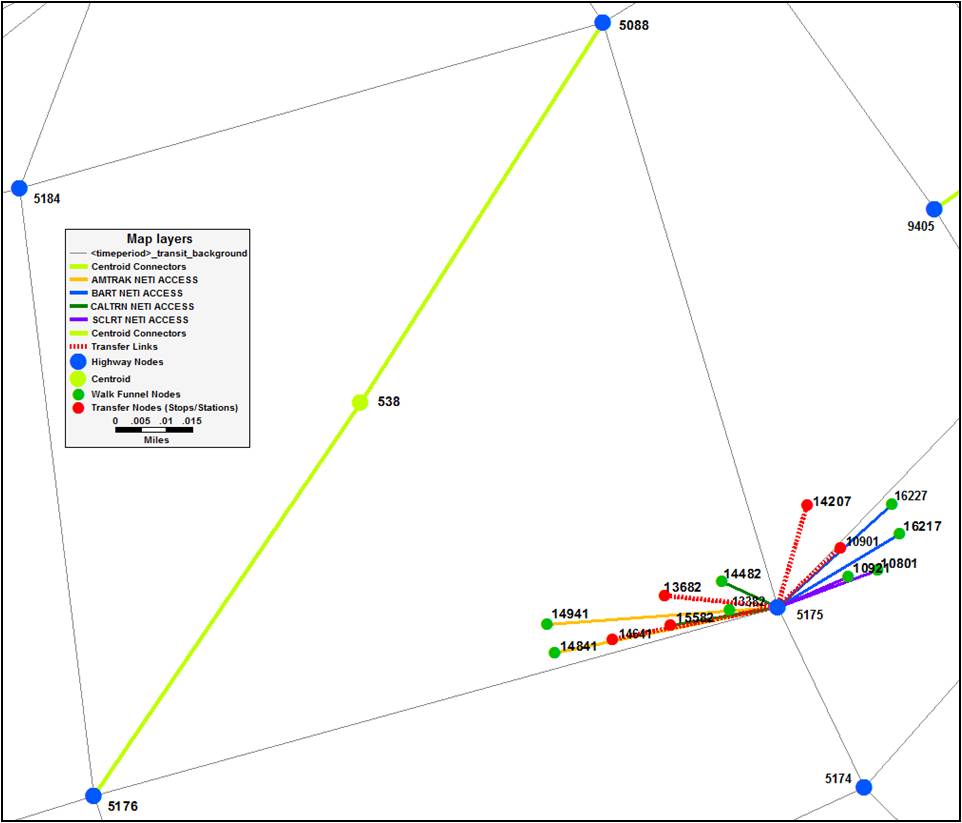
Figure 1 illustrates the transit access link mode coding for an example rail stop and some adjacent bus stops. The rail line is "off-network", meaning that it does not exist in the highway network (.net) file, but is instead defined in the transit-only links specified in the transit line files (.tpl). The bus routes operate on the highway network, and are represented in the transit line files as a sequence of node IDs.
The drive access funnel link (mode=4) forces all park and ride (PNR) trips to a specific stop or station to go through that funnel link. A single drive access funnel link may be connected to multiple zonal drive connectors (mode=2) links going to diferent TAZs. This coding ensures that the number of PNR trips to a specific stop or station can easily be summarized. The walk funnel links (mode=5) serve a similar purpose for off-network rail stations. That is, by forcing all zonal walk access connectors (mode=1) through a single funnel link, the total number of direct walk access and egress trips to a particular station can be easily tabulated from the results. Any remaining trips to a station, beyond those on the drive and walk access funnel links must be transfers, and therefore must traverse a transfer link (mode=3). Unlike the funnel links, of which there can be only one to a specific station, there can be many transfer links to/from a particular station connecting to any other stations or stops within the transfer link generation threshold. The on-network bus stops may use drive access funnel links, but do not use walk-access funnel links. Instead, zonal walk connectors (mode=1) are generated directly to the on-network bus stops.
The zonal walk connectors (mode=1), zonal drive connectors (mode=2), and transfer links (mode=3) are generated automatically in the script buildTransitNetwork.job. The drive funnel link (mode=4) is generated based on the parameters specified on the <Operator>.PNR file. The walk funnel link (mode=5) must be coded manually in the file <Operator>.ZAC
Two additional link types are of importance for the off-network station coding: background transit access dummy links (specified in the file <Operator>_NETI_ACCESS_LINKS.DAT), and background transit transfer dummy links (specified in the file <Operator>_NETI_XFER_LINKS.DAT). These links facilitate the automatic generation of walk access connector (mode 1), drive access connector (mode 2), and station-station transfer (mode 3) links. In order for buildTransitNetwork.job to auto-generate access and transfer links, it must be able to trace a path in the background highway network between centroids and transit stations. All dummy nodes (the non-transit stop end of funnel links) and transit stop nodes that are coded on transit-only links must be connected to the highway network in order for the script to work. For example, to generate the zonal walk connector 538-14941, the script must be able to trace the path 538-5175-14941 through the highway network. 538-5175 already exists as a centroid connector, but 5175-14941 does not pre-exist in the highway network, which is a problem. In order to get around this issue, a dummy access link 5175-14941 must be specified in file <Operator>_NETI_ACCESS_LINKS.DAT to connect the highway node to the walk funnel node (or a drive funnel node). Similarly, a dummy transfer link 5175-14641 must be specified in file <Operator>_NETI_XFER_LINKS.DAT to allow transfer links to be auto generated from the highway stop node to/from the station node. The script prepHwyNet.job adds these links to the background highway networks such that buildTransitNetwork.job can successfully trace the path when auto-generating walk-access, drive-access and transfer links.
This dummy link coding is only needed when connecting to nodes that do not pre-exist in the highway network. In this way, walk access links and transfer links to bus stops are generated without further intervention. It is also worth noting that when these links are auto generated, they are given the distance that is traced from the background highway network, as opposed to the straight-line distance of the generated link itself. In this way, the resolution of the network and the specific coding of centroid connectors can influence the walk access times, as well as which links get generated.
Table 3 lists the input and output files used in the creation of the transit access/egress/transfer links. Each of these files is explained in the sections that follow.
Figure 1 Transit Network Coding Example
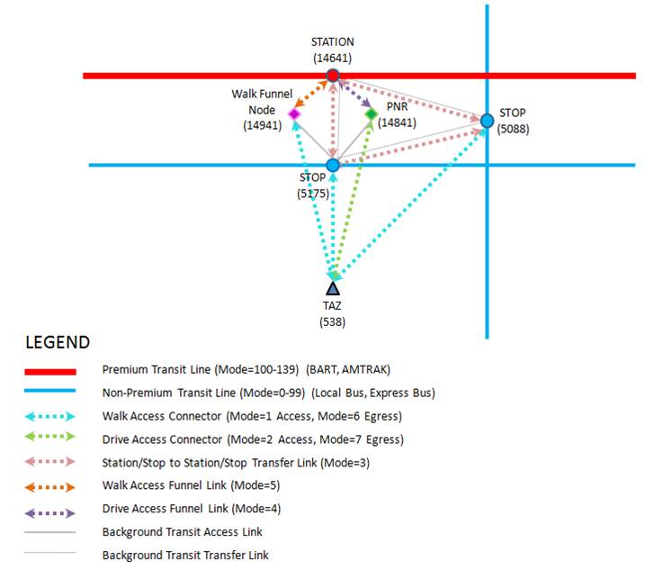
Table 3 Transit Network Modes
| Input/Output | Mode | Link | File |
|---|---|---|---|
| I | 1, 6 | stop – walk funnel (5175 - 14941) | <Operator>_NETI_ACCESS_LINKS.DAT |
| I | 2, 7 | stop – PNR lot (5175 - 14841) | <Operator>_NETI_ACCESS_LINKS.DAT |
| I | 1 | zone – stop (538-5175) | walk_access.sup |
| I | 3 | stop – station (5175 - 14641) | <Operator>_NETI_XFER_LINKS.DAT |
| I | 4 | PNR lot – station (14841– 14641) | <Operator>.PNR |
| I | 5 | walk funnel – station (14941 - 14641) | <Operator>.ZAC |
| O | 1, 6 | zone – stop (538-5175) | <timeperiod>_transit_suplinks.dat |
| O | 2, 7 | zone – PNR lot (538 - 14841) | <timeperiod>_transit_suplinks.dat |
| O | 3, 4, 5 | stop – station (5175 - 14641) | <timeperiod>_transit_suplinks.dat |
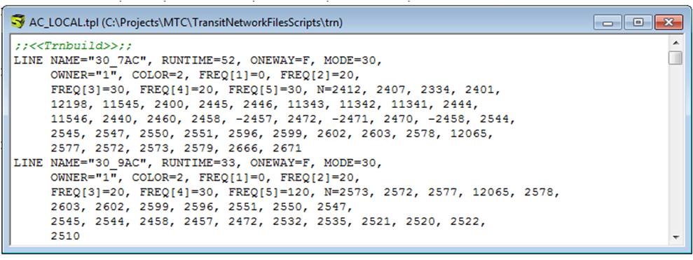
The transit lines are specified in a series of files ending with the extension .tpl, organized by transit operator and line-haul mode. For example, AC transit operates two types of transit lines (or technologies): local bus as specified in AC_Local.tpl and express bus as specified in AC_TransBay.tpl. Figure 2 shows an example of the transit line file. A name is assigned to each route based on the operator mode and a description of the route, usually the line number and the direction of the route if necessary. Attributes of the transit lines include runtime, stop node sequence, line-haul mode, and headways by time period (FREQ[1-5] which refer to Early AM, AM Peak, Midday, PM Peak, and Evening respectively). The sequence of nodes specify the path of the route, where the node numbers correspond to the nodes in the highway network. Consult the Cube manual for details on the specification of the transit line files. The relationship to the highway network will be discussed in [[#TransitBackgroundFiles][transit background network]] section below.
Figure 2 Transit Line File Example
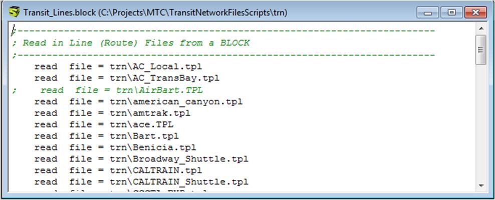
The current MTC model has 34 transit operators and 46 transit line files. To avoid having to update the script that builds the transit network whenever a new line file is added, the transit line files are specified in a transit block file (transit_line.block) that is read in by Cube when running the transit network build script. As a result, whenever a new transit operator is added to the model, the analyst must create a new transit line file, with the <operator>_<line-haul mode>.tpl filename and then add it to the transit block file (transit_line.block). Figure 3 shows the transit_line.block file.
Figure 3 Transit Line Block File (Transit_line.block)
It is important to note that some transit segments are not included in the highway network. This is the case for rail lines, ferries or dedicated lanes used only by buses (for example, the bus ramps between the Bay Bridge and the Transbay Terminal). These links are transit-only links and are coded in the .tpl file of the respective operator and mode. The link should include information about the time and distance between nodes, as well as the transit modes that can travel the link. These may need to be updated as well when coding/modifying the transit network.
The transit networks are built in two steps:
- By creating the transit network files from the highway network and relevant transit files for the 5 time periods.
- By generating the access, egress, and transfer support links from the transit network and other support files.
The transit network files are the highway network files with bus speeds, transit access links, transit transfer links, walk funnel links, and drive funnel links which are added by the PrepHwyNet.job script. There are two types of temporary transit networks that are created by this script, as follows:
- <time period>_temporary_transit_background_accesslinks.net - Highway network with transit access links (see Figure 1, above) between:
- Highway nodes and walk access funnel nodes
- Highway nodes and PNR lots
- <time_period>_temporary_transit_background_transferlinks.net - Highway network with transfer links (see Figure 1, above) between:
- Highway nodes and transit stations
- Highway nodes and PNR lots
The script "PrepHwyNet.job" performs the following three steps:
- Computes the bus travel time on every highway link by assuming a fixed delay (in minutes per mile), segmented by link area type (AT) and facility type (FT). Links with speeds below a minimum threshold (2 MPH) are set to that minimum threshold to help the path builder find valid paths. This step also adds transit-only nodes to the highway network which are needed for the second and third steps in the script.
- Transit access links are added to the highway network. This is necessary for Cube to automatically generate walk and drive access links in a later step.
- Transit transfer links are added to the highway network. This is necessary for Cube to automatically generate transfer access links in a later step.
Two new variables, BUS_TIME and PNR_TIME, are computed from the highway variables PNROK, CTIM, FT and AT in the first step. Table 4 and Table 5 show the input attributes and files used in computing the bus travel times and park and ride times in this first step. The transit support nodes input file (transit_support_nodes.dat) consists of transit-only nodes (PNR nodes, walk funnel nodes, and transit nodes that are not part of the highway network such as a grade-separated rail line) as shown in Figure 4. The file consists of nodes not on the highway network and each node is defined by a node number, an x coordinate, and a y coordinate.
Table 4 Bus Travel Time and Park and Ride Time Input Attributes
| Variable | Description | Example |
|---|---|---|
| PNROK | 1=link can be used as PNR access, 0 = cannot be used | 1 or 0 |
| CTIM | Congested Travel Time | 5.67 |
| FT | Facility Type | 1,2,..9 |
| AT | Area Type | 0,1,..5 |
| DISTANCE | Link Distance (miles) | 1.45 |
Table 5 Input and Output Files used in Computing BUS_TIME and PNR_TIME
| Input/ Output | File | Description | Example |
|---|---|---|---|
| I | Input Highway Network | Highway network with key variables | avgload<timeperiod>.net |
| I | Input Transit Only Nodes | Additional transit nodes that do not exist in the highway network | transit_support_nodes.dat |
| O | Output Transit Background Network | A time-period-specific transit background network with PNR_TIME and BUS_TIME | <timeperiod>_transit_background.net |
Figure 4 Transit Support Nodes Transit Support File (Transit_Support_Nodes.DAT)

The second step consists of adding the background transit access links to the transit networks produced in the above step. The input access links are specified in separate files by operator, where the file name is a concatenation of the operator and "_neti_access_links.dat" - except for the transit access links for the local bus mode, which are specified in "bus_neti_access_links.dat". Figure 5 shows a transit access link support file and Table 6 shows the list of transit access link files that the analyst is required to input as well as the output file from this step. The input access links file consists of two columns: A-NODE and B-NODE, as shown in Table 7. These represent highway nodes and walk access funnel nodes\PNR lot funnel nodes respectively.
Figure 5 Transit Access Links By Operator Transit Support File (<Operator>_NETI_ACCESS_LINKS.DAT)

Table 6 List of Inputs and Output Files Used in Adding Transit Access Links
| Input/ Output | File | Description | Example |
|---|---|---|---|
| I | Input Access Link File | Amtrak access links | amtrak_neti_access_links.dat |
| I | Input Access Link File | Bart access links | bart_neti_access_links.dat |
| I | Input Access Link File | Caltrain access links | caltr_neti_access_links.dat |
| I | Input Access Link File | Sclrt access links | sclrt_neti_access_links.dat |
| I | Input Access Link File | Muni access links | munimet_neti_access_links.dat |
| I | Input Access Link File | Ferry access links | ferry_neti_access_links.dat |
| I | Input Access Link File | Bus access links that are not in the highway network | bus_neti_access_links.dat |
| I | Input Transit Background Network | A time-period-specific transit background network with PNR_TIME and BUS_TIME | <timeperiod>_transit_background.net |
| O | Output Transit Background Access Network | A time-period-specific transit background network with PNR_TIME, BUS_TIME and background transit access links | <timeperiod>_temporary_transit_background_accesslinks.net |
Table 7 Transit-Only Access Link File Data Fields/Columns
| Variable | Description | Example |
|---|---|---|
| A | highway network node | 11122 |
| B | walk or PNR funnel node | 14956 |
The third step consists of adding the transit transfer links to the highway network. Similar to the transit access links, the transit transfer links are added to the transit networks. The input transfer link are specified in separate files by operator, where the file name is a concatenation of the operator and "_neti_xfer_links.dat"- except for the transit access links for the PNR lots, which are specified in "bus_neti_xfer_links.dat". Figure 6 shows a transit transfer line support file and Table 9 lists inputs and outputs to this step. The input transfer link files consist of A-NODE B-NODE pairs that are used to create transfer links. Table 10 shows the key variables in the transit transfer link files.
Figure 6 Transfer Links By Operator Transit Support File (<Operator>_NETI_XFER_LINKS.DAT)

Table 9 Input and Output Files Used in Adding Transit Transfer Links
| Input/ Output | File | Description | Example |
|---|---|---|---|
| I | Input Transfer Link File | Amtrak transfer links | amtrak_neti_xfer_links.dat |
| I | Input Transfer Link File | Bart transfer links | bart_neti_xfer_links.dat |
| I | Input Transfer Link File | Caltrain transfer links | caltr_neti_xfer_links.dat |
| I | Input Transfer Link File | Sclrt transfer links | sclrt_neti_xfer_links.dat |
| I | Input Transfer Link File | Muni transfer links | munimet_neti_xfer_links.dat |
| I | Input Transfer Link File | Ferry transfer links | ferry_neti_xfer_links.dat |
| I | Input Transfer Link File | Bus transfer links that are not in the highway network | bus_neti_xfer_links.dat |
| I | Input Transit Background Network | A time-period-specific transit background network with PNR_TIME, BUS_TIME | <timeperiod>_transit_background.net |
| O | Output Transit Background Access Network | A time-period-specific transit background network with PNR_TIME, BUS_TIME, and transit access and transfer links | <timeperiod>_temporary_transit_background_transferlinks.net |
Table 10 Transit Transfer Link File Data Fields/Columns
| Variable | Description | Example |
|---|---|---|
| A | node on the highway network | 5175 |
| B | stop on a transit line | 14641 |
| Distance | Distance between A-node and B-node in miles | 0.5 |
Figure 7 and Figure 8 show an example of the input and output networks from the script PrepHwyNet.job, where the access link from the highway network node 5175 is connected to the walk access funnel node 14941.
Figure 7 Input Network Before Running PrepHwyNet.job
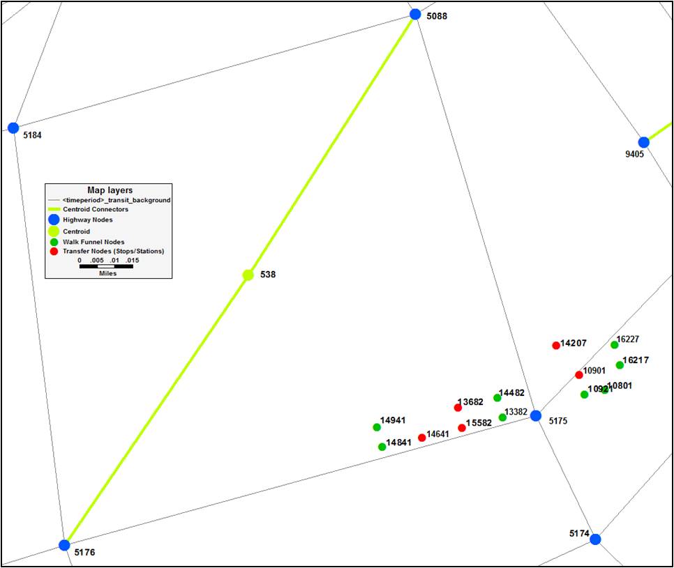
Figure 8 Output Network After Running PrepHwyNet.job
The zonal walk and drive access and egress connectors, as well as the transfer links, are generated automatically via the script buildTransitNetwork.job. The script invokes the Cube Transit Path Builder function and generates the access and egress connectors, as well as the transfer links. The script is run five times, once for each time period.
The access and egress connectors and transfer links are built via the following five steps:
- Walk access connectors are generated that connect zone centroids to bus stops (on the highway network) and walk funnel nodes.
- Drive access connectors are generated that connect zone centroids to park-and-ride funnel nodes.
- Gawk is used to turn the access connectors generated in step 1 into egress connectors by reversing the a-node and b-node and writing out a separate file.
- Based on the transit transfer link files (<Operator>_NETI_XFER_LINKS.DAT), transit network files and transit line files, Cube builds paths and generates the transit transfer links between any two transit stations or bus stops that are within 0.75 miles of each other. The transfer links are also merged with the access and egress links in this step to create one output file (<timeperiod>_transit_suplinks.dat).
- Gawk is used to select the two best park-and-ride lots for each zone in terms of distance for each of type of line haul facility that has park-and-ride lots.
The walk access and drive access connector creation step requires the user to input the walk and drive funnel links described earlier. These funnel links are defined in the <Operator>.ZAC file (see [Figure 9]) for walk access funnel links and <Operator.PNR> (see Figure 10) for drive access funnel links. The walk funnel links are defined by an A-NODE, B-NODE and mode (which is equal to 5). The drive funnel links are defined by an A-NODE, B-NODE, travel time, and applicable zone set (which is set to all zones). The additional walk access link file (walk_access.sup) consists of hand-coded walk access links from zones to selected bus stops or transit stations that are not on the network. It is used as an over-ride to the automated access link coding process. The file is shown in Figure 11. These supplemental links are defined by an A-NODE, B-NODE, mode (which is mode 1 for walk access), and include a distance and speed attribute. Tables 12 - 16 describes the inputs and outputs of each step of this script.
Figure 9 Walk Access Funnel Links File (<Operator>.ZAC)

Figure 10 Drive Access Funnel Links File (<Operator>.PNR)

Figure 11 Additional Walk Access Links File (walk_access.sup)

Table 12 Create Walk Access Connectors Inputs/Outputs
| Input/ Output | Name | Description | Examples |
|---|---|---|---|
| I | Background Transit Network | A transit background network that contains all the walk access funnel links | <Time period>_temporary_transit_background_accesslinks.net |
| I | Walk Access Funnel Links | Walk access funnel links (mode=5) | amtrak.zac (<provider>.zac) |
| I | Transit Lines | Transit stop locations file | transit_lines.block |
| I | Walk Access Links | Additional hand-coded walk access links | walk_access.sup |
| O | Zonal Walk Access Connectors | Zonal Walk Access Connectors in DBF Format | <time_period>_walk_links.dbf |
| O | Zonal Walk Access Connectors | Zonal Walk Access Connectors in TXT Format (mode=1) | <time_period>_walk_acclinks.dat |
Table 13 Create Drive Access Connector Inputs/Outputs
| Input/ Output | Name | Description | Examples |
|---|---|---|---|
| I | Background Transit Network | A transit background network that contains all the drive access funnel links | <Time period>_temporary_transit_background_accesslinks.net |
| I | Drive Access Funnel Links | Drive funnel link files (mode=4) | amtrak.PNR (<provider>.PNR) |
| I | Transit Lines | Dummy transit line files | muni_local.tpl |
| O | Zonal Drive Access Connectors | Zonal Drive Access Connectors in DBF Format | <time_period>_drive_links.dbf |
| O | Zonal Drive Access Connectors | Zonal Drive Access Connectors in TXT Format (mode=2) | <time_period>_drive_acclinks.dat |
Table 14 Gawk Egress Link Creation Inputs/Outputs
| Input/ Output | Name | Description | Examples |
|---|---|---|---|
| I | Zonal Walk Access Connectors | Zonal Walk Access Connectors in DBF Format (mode=1) | <time_period>_walk_acclinks.dat |
| I | Zonal Drive Access Connectors | Zonal Drive Access Connectors in TXT Format (mode=2) | <time_period>_drive_acclinks.dat |
| O | Zonal Walk Egress Connectors | Zonal Walk Egress Connectors in DBF Format (mode=6) | <time_period>_walk_egrlinks.dat |
| O | Zonal Drive Egress Connectors | Zonal Drive Egress Connectors in TXT Format (mode=7) | <time_period>_drive_egrlinks.dat |
Table 15 Create Transfer Links And Merge With Access and Egress Connectors Inputs/Outputs
| Input/ Output | Name | Description | Examples |
|---|---|---|---|
| I | Background Transit Network | A transit background network that contains all the transfer links | <Time period>_temporary_transit_background_transferlinks.net |
| I | Zonal Walk Access Connectors | Zonal Walk Access Connectors in TXT Format (mode=1) | <time_period>_walk_acclinks.dat |
| I | Zonal Drive Access Connectors | Zonal Drive Access Connectors in TXT Format (mode=2) | <time_period>_drive_acclinks.dat |
| I | Zonal Walk Egress Connectors | Zonal Walk Egress Connectors in TXT Format (mode=6) | <time_period>_walk_egrlinks.dat |
| I | Zonal Drive Egress Connectors | Zonal Drive Egress Connectors in TXT Format (mode=7) | <time_period>_drive_egrlinks.dat |
| I | Transit Lines | Transit line file | transit_lines.block |
| O | Transfer Links | Transfer Links in DBF Format (mode=3) | <time_period>_transit_links.dbf |
| O | Auxiliary Links | Access Connectors, Egress Connectors, and Transfer Links (mode=1,2,3,6,7) | <time_period>_transit_suplinks.dat |
Table 16 Gawk Drive Access Link Reduction Inputs/Outputs
| Input/ Output | Name | Description | Examples |
|---|---|---|---|
| I | Auxiliary Links | Auxiliary Links in TXT Format | <time_period>_transit_suplinks.dat |
| O | Auxiliary Links by <operator> | Auxiliary Links by operator such as BART | <time_period>transit_suplinks<operator>.dat |
The transit fares are specified in separate files denoted with the “.FAR” extension. The fares are specified in year 2000 cents. There are four types of fare formats used in the MTC model:
Direct fares are the initial boarding fares for riding a transit line. Direct fares are specified in the xfare.far file. This file lists both the initial and transfer fares in a matrix form of 137 X 137 transit modes (a combination of modes and operators). From this matrix, the initial fare and transfer fares are read into MODEFARE and XFARE variables of TP+ program respectively. The MODEFARE is an array of fares coded to auxiliary-transit links (walk access connector, drive access connector, walk funnel links) for all the transit modes and is used as an initial boarding fare. The XFARE is an array of transfer fares between all modes including auxiliary-transit to transit mode fares (same as MODEFARE). During path building, for the first boarding, the auxiliary-transit to transit MODEFARE value is read as the initial boarding fare instead of the XFARE auxiliary- transit to transit mode. For the subsequent boardings (transfers to another transit mode), the XFARE value for that mode pair is used as the transfer fare.
The transfer fares are explained in the Transfer Fares section below. The initial boarding fares between transit modes to auxiliary-transit modes and auxiliary-transit modes to auxiliary-transit modes are specified as zeros. For some premium transit modes (modes 100-109 and 120-137) the initial fares are also specified as zeros and are substituted with a station-to-station fares, which are described under the Station-to-Station Fares section below.
Figure 12 Transit Fare File (xfare.far)

The xfare.far file is cumbersome to develop/edit in Cube or a text editor. To make developing/editing the fare matrix easier, MTC developed the MODES_&_FARES_2016.xlsx Excel file with the following three tabs:
- 2015 Fares
- 2015 Fares Conv
- xfare table
The tab "2015 Fares" lists both the initial and transfer fares among all modes in 2016 year cents. The fares were reviewed for 2016, but the tab names were not updated. In this file some of the premium modes (modes 100-109 and 120-137) are specified with a zero initial and transfer fare between the same mode. However, the transfer fare between the different premium modes is listed here since the station-to-station files apply only the transfer fares between the same modes. The tab "2015 Fares Conv" converts all the fares from 2016 to 2000 year cents by applying the consumer price index (CPI) factor. The tab "XFARE Table" reads the 2000 fares and formats them into a Cube readable file. This tab is then saved as xfare.far.
The transfer fares are fares that are charged when a transfer from one transit line to another occurs. These fares are also specified in the same xfare.far file. The transfer fares between the same premium transit mode (modes 100-109 and 120-137) are specified as zero since the station-to-station fares actually count these transfer fares. Additional transfer fare files are specified to represent a county-to-county transit system transfer, which are described in detail in the Link Based Fares section.
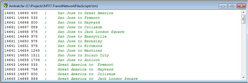
The premium transit lines (modes 100-109 and 120 -137) charge fares between stations. These fares are specified in the <operator>.FAR files. For example, the BART.FAR file consists of fares between all BART stations. Figure 13 shows a sample station-to-station fare file.
Figure 13 Transit Station-to-Station Fare File (<Operator>.FAR)
Some fare structures are provided between zones. Many times is hard to capture the exact fare using the methods explained above. In those cases we use the command FARELINK. This command adds a specific amount indicated in the FARELINK command to the basic fare as a link is traversed in a path. These links are included in the Farelinks.far file.
Figure 14 Transit Link Based Fare File (Farelinks.far)

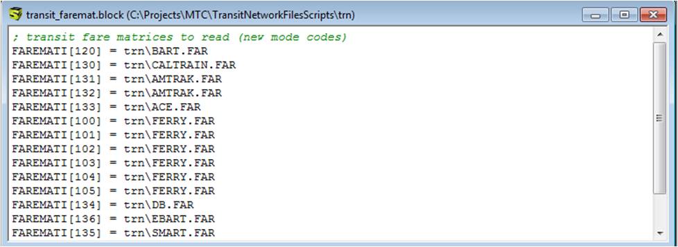
Similar to the transit line block file, all transit fares are specified in a block file that is read in by the script at runtime as shown in Figure 15.
Figure 15 Transit Fare Block (Transit_faremat.block)
Previously the MTC/ABAG Analytical Modeling Wiki (http://analytics.mtc.ca.gov/foswiki/Main/WebHome)
Please email lzorn@bayareametro.gov if you find anything missing here.