Amplifier Pepper
Dedicated PCB for improving the signal-to-noise ratio of the audio outs on the first rev of Pepper. Please email robert (@) bela.io if you would like one. Please note that this is not the easiest board to install and we recommend this only for confident module builders, as it is a tight fit between the Pepper PCB and Bela cape and may require desoldering.
See forum for full discussion: https://forum.bela.io/d/973-switching-noise-pepper/19
This board amplifies the audio output using the balanced outputs from Bela. The end voltage range of the audio output is -5V to 5V.
BOM from Mouser is here: https://www.mouser.com/ProjectManager/ProjectDetail.aspx?AccessID=0594fa4c66
We use a NE5532AP op amp plus the necessary resistors and capacitors. The only other special component is the half height headers which we use to squeeze this board between the Pepper PCB and Bela cape.
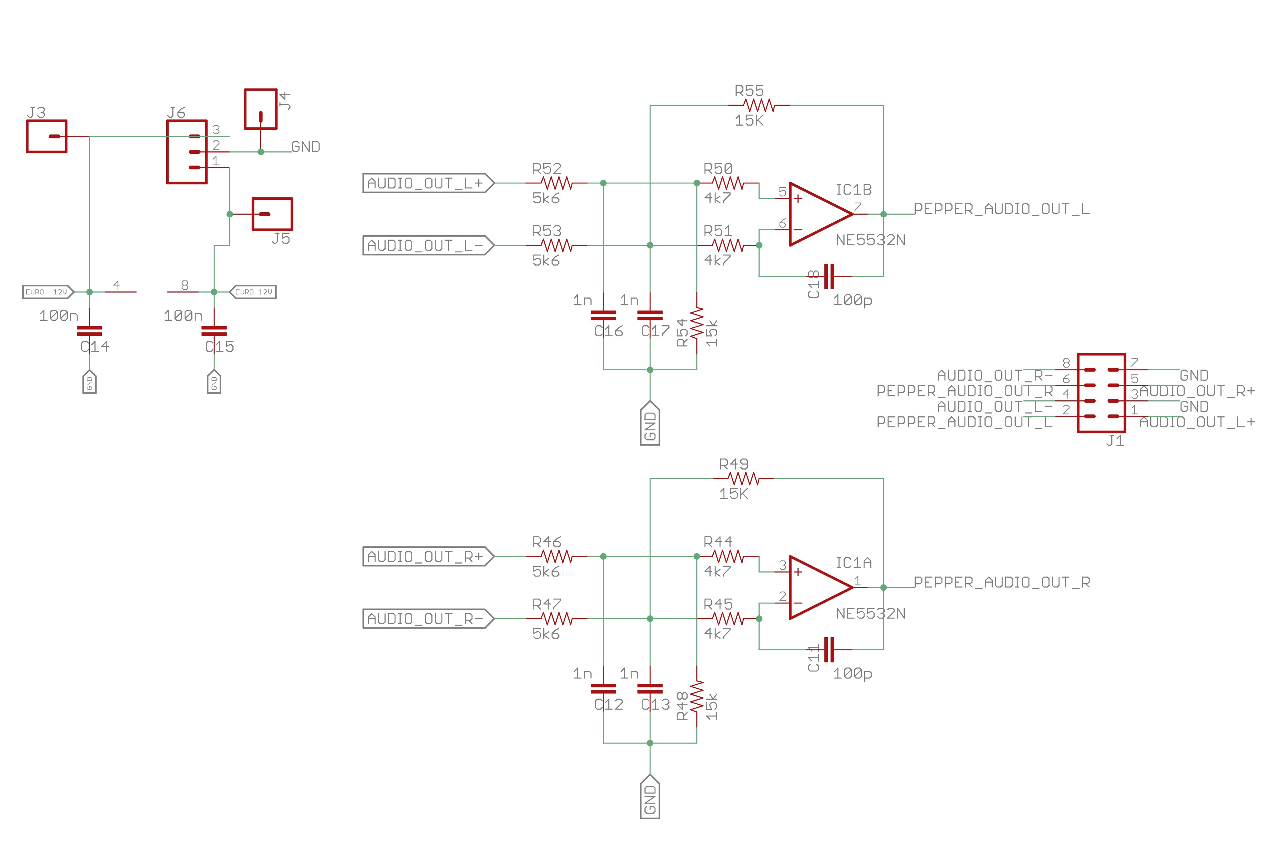
Here's the schematic with resistor and capacitor values:
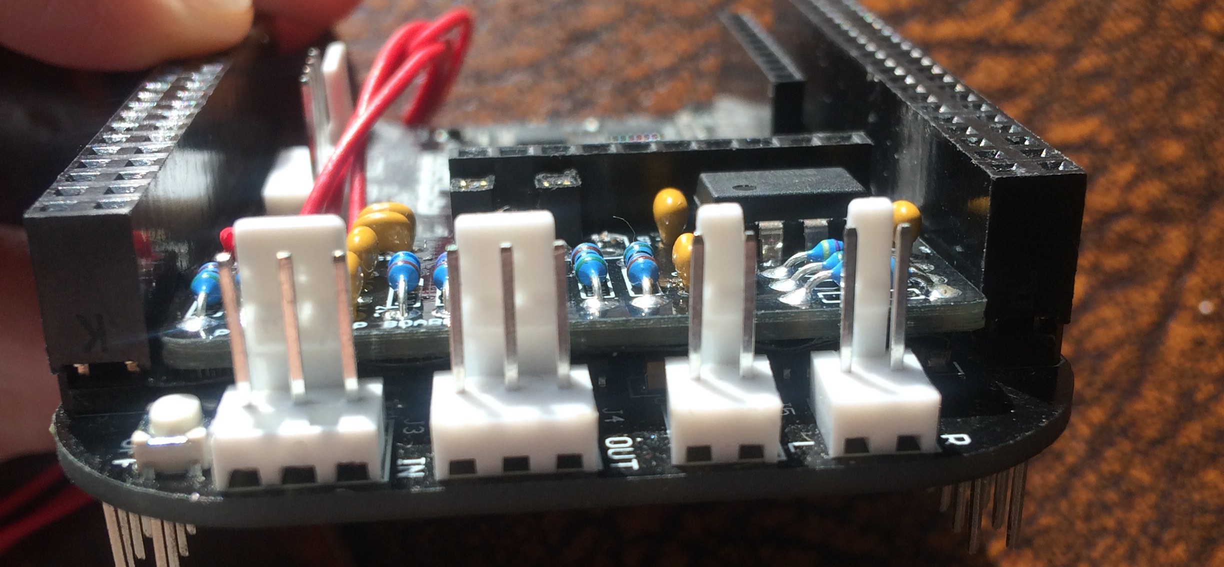
Here's a photo of the board with all parts soldered:
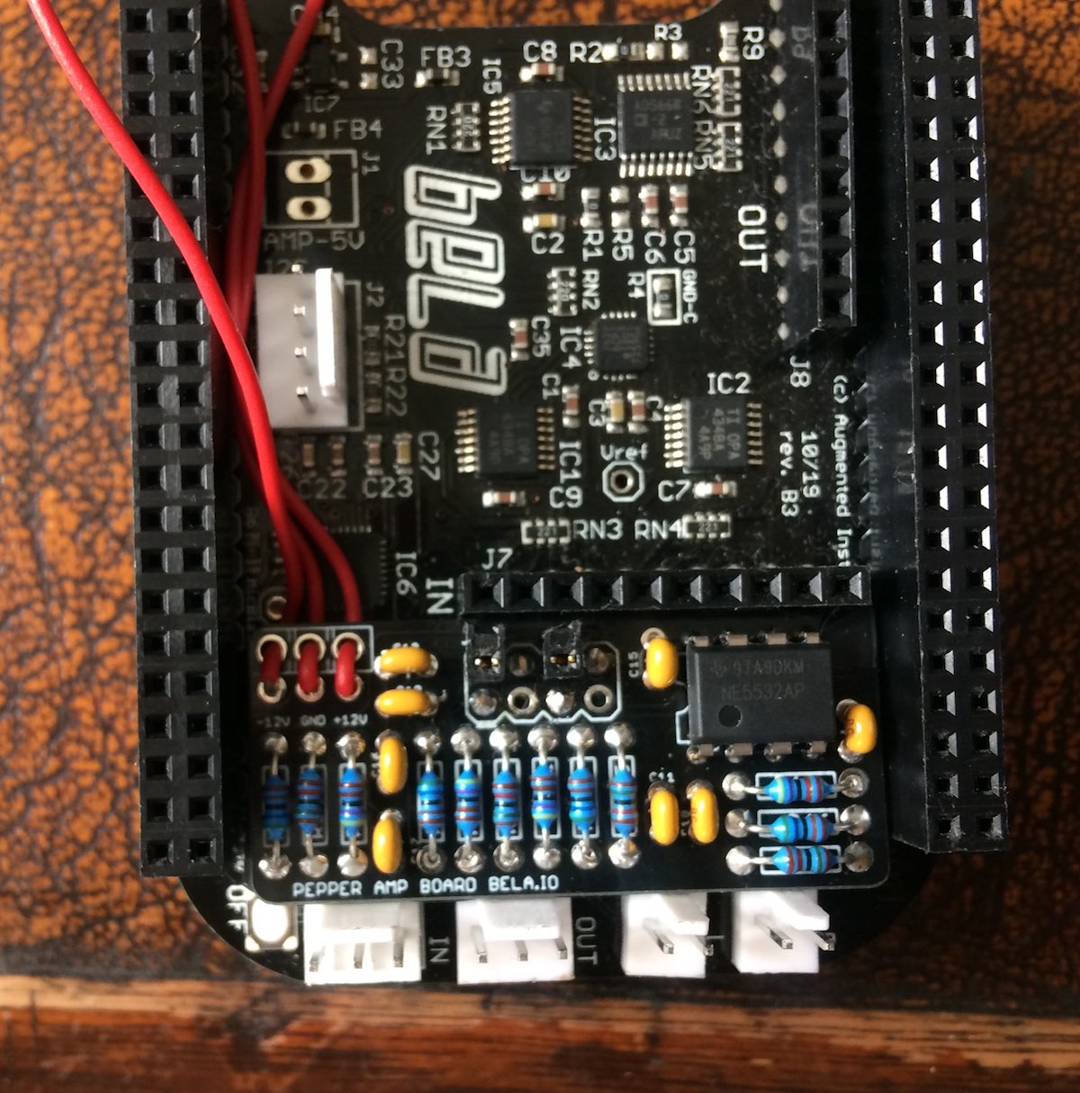
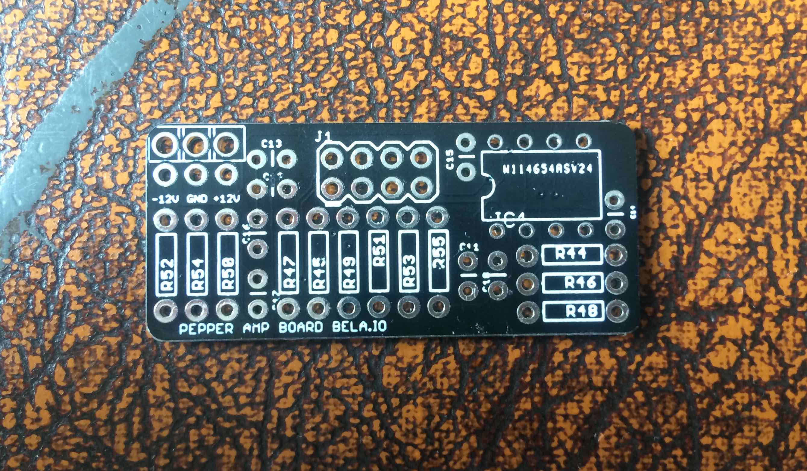
There are power connections on the left hand side of the board. These are two rows per connection. We suggest using the outer holes to anchor the wire and soldering to the inner holes as in the picture.
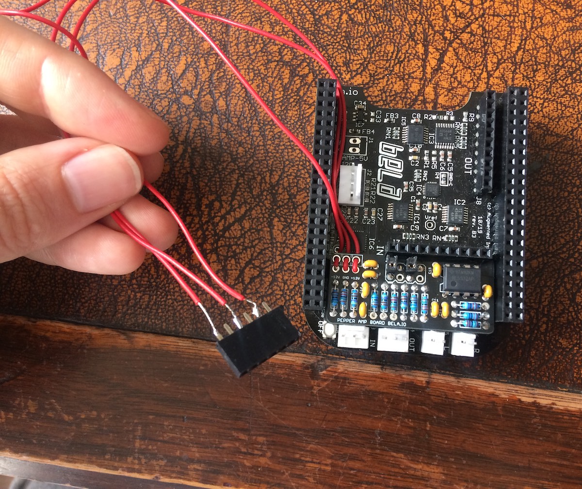
We found that the easiest way to the required +/-12V and Ground to the board was to solder these pads to wire which then connect to a header which is plugged into your Eurorack power bus. As ever when plugging things into the power bus DOUBLE CHECK that the pins are aligned correctly.
The schematic for the board can be seen at the top of this page. The differential gain is 15k/5.6k, that is a factor of 2.68.
To test this board you can you use the GND (0V) and 3.3V signals available from Bela. If you apply 3.3V to the + input and 0V to the - input of a channel you should be able to read 3.3V * 2.68 = 8.84V at the output. Check with a multimeter in DC voltage mode. Conversely, applying 3.3V to the - input and 0V to the + input should give -3.3V * 2.68 = -8.84V at the output. Once verified then you're ready to install.
The 2 half height headers will connect with the Pepper PCB.
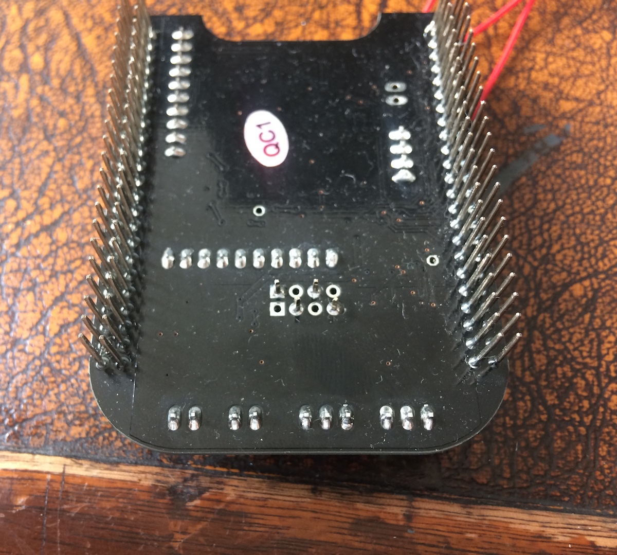
On the bottom of the amp board the 4 pins will connect to the balanced audio output of Bela and will need to be soldered in place. It's a tight fit so we recommend soldering to the Bela cape as the very last step once you have fitted the Pepper PCB onto the Bela cape with the amp board sandwiched in between.
You will also need to desolder the 3 pin female socket header on the line output of the Bela cape if you already attached it.
As a reference the connection of header are as follows if you are looking at the amp board on the cape in the same orientation as the above pictures:
| o | • | o | • |
| • | x | • | x |

where o means “half-height socket” up to Pepper, x = not connected, • means pin down to Bela cape.