-
Notifications
You must be signed in to change notification settings - Fork 1
plugging
HOME > TECHNICAL INFO: PLUGGING
The sections below list the objects and their attached sensors and attributes.
Properties
Properties can be found in the rosparam server under the depicted name. To get the full path, run rosparam list | grep PROPERTY_NAME while the simulation runs.
Sensors
Sensor topics can be listened to from the command line by running rostopic echo /PATH/TO/SENSOR, e.g., rostopic echo /plug_pos.
Each sensor publishes a second topic without noise if testing mode is active. These topics can be reached by simply appending the _GT suffix to the topic path.
Note: The higher you choose the difficulty level, the less information you are provided with and the noisier the sensors get.
Difficulty levels
There are 4 levels of difficulty for the plugging task:
Difficulty 1 (baseline)
Cylindrical plug geometry
Slight overall sensor noise
No offset perturbation to the frame's pose
Hight friction gripper fingers
Difficulty 2 (localization)
Varying plug geometry
Realistic overall sensor noise
Offset perturbation to the frame's pose
Hight friction gripper fingers
Difficulty 3 (slippage)
Varying plug geometry
Realistic overall sensor noise
No offset perturbation to the frame's pose
Medium friction gripper fingers
Difficulty 4 (combined)
Varying plug geometry
Realistic overall sensor noise
Offset perturbation to the frame's pose
Medium friction gripper fingers
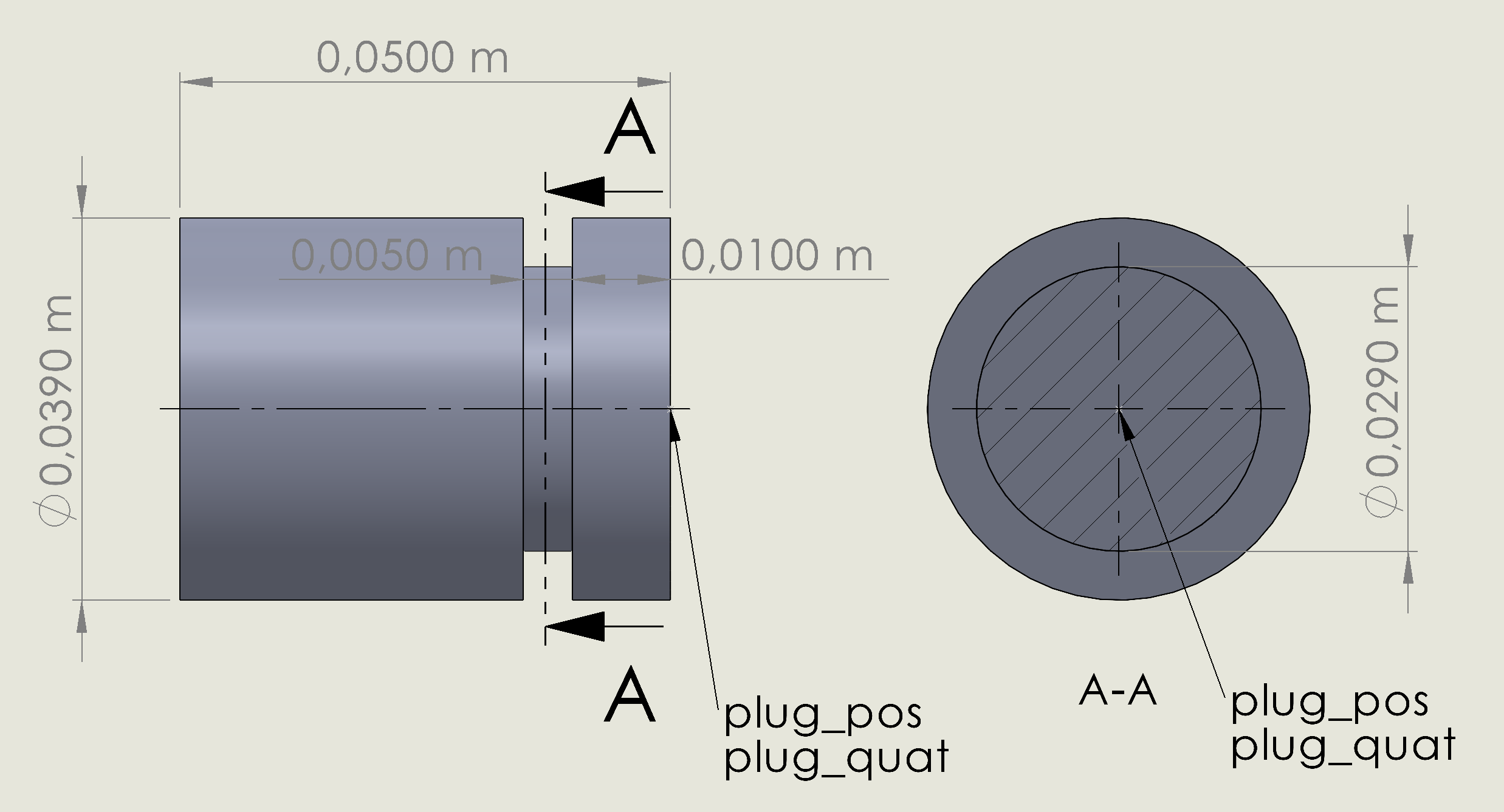
The following images display the dimensions of the different plug geometries. In the simulated scene, the plug's position and orientation are available via the /plug_pos and /plug_quat rostopics. The values streamed correspond to the position and orientation of the frame attached to the plug at its bottom middle point (see pictures). For the axes and the orientation of this frame, see the section on the fixtures -- when assembled, the plug's 6D pose should be the same as that of the fixture.
The actual meshes are available from the /home/assembly_server/share/assembly_demo/assets/meshes/plugging/collision directory in the challenge docker image. The meshes are split into convex sub-meshes due to the simulator's collision-checking algorithm; the parts that belong together follow the naming convention 2023_icra_challenge_<GEOMETRY TYPE>_plug_<NUM>.STL, where <GEOMETRY TYPE> is either cylindrical, cuboid or triangular, and <NUM> is the integer ID of the sub-mesh. The sub-meshes were exported with the same origin, so re-composing them should be possible by only importing them into the same project/environment (e.g. via Blender).


The following images display the dimensions of the different fixture geometries. In the simulated scene, the fixture's (perturbed/offset) position and orientation are available via the /fixture_pos and /fixture_quat rostopics. In training mode, the actual position and orientation are available via the /goal_pos and goal_quat rostopics. The values streamed correspond to the position and orientation of the frame that is attached to the fixture at its bottom middle point (see pictures). The axis z of this frame is the direction of the plug insertion and points bottom-up, and the axis x is parallel to the longest dimension of the fixture.
The actual meshes are available from the /home/assembly_server/share/assembly_demo/assets/meshes/plugging/collision directory in the challenge docker image. The meshes are split into convex sub-meshes due to the simulator's collision-checking algorithm; the parts that belong together follow the naming convention 2023_icra_challenge_<GEOMETRY TYPE>_<ID>.STL, where <GEOMETRY TYPE> is either cylindrical, cuboid or triangular, and <ID> is either an integer ID for the sub-mesh or an ID in the form of 3_<NUM> in the case of the cylindrical fixture. The sub-meshes were exported with the same origin, so re-composing them should be possible by only importing them into the same project/environment (e.g. via Blender).


For the scoring, the sub-tasks are weighted as shown in the following table:
| sub-task | weight |
|---|---|
| Pick up the plug | 10 |
| Localize the frame | 35 |
| Align the plug into the frame | 35 |
| Click-insert the plug | 20 |
Each sub-task must be completed within 30 seconds; otherwise, the whole run will be terminated prematurely during evaluation.
The task will be evaluated for a fixed number of iterations on each difficulty level. Initial poses of objects will be randomized across iterations but identical for all participants. The total score is aggregated as the weighted sum of all successfully completed sub-tasks over all iterations, as shown in the following equation,
where
In the case of ties, we break them by dividing the scores by the sum of the weighted time the solutions took to achieve them, i.e.,
where
Both gripper fingers are in contact with the plug.
Either one of the gripper fingers or the plug is in contact with the frame.
The plug's bottom middle point is
- within 0.002 meters (2 millimetres) of the fixture's middle point (hole) along the axes x and y and
- is up to 0.052 meters (52 millimetres) above the fixture's bottom middle point.
The plug's bottom middle point is within 0.002 meters (2 millimetres) of the fixture's bottom middle point along all axes.
Home / Setup Guide / Interfacing the Sim
Copyright © 2023 Universität Bielefeld, Fraunhofer Institute for Manufacturing Engineering and Automation IPA