-
Notifications
You must be signed in to change notification settings - Fork 40
Tutorial 11: DMM multi access ARCFIRE 2018
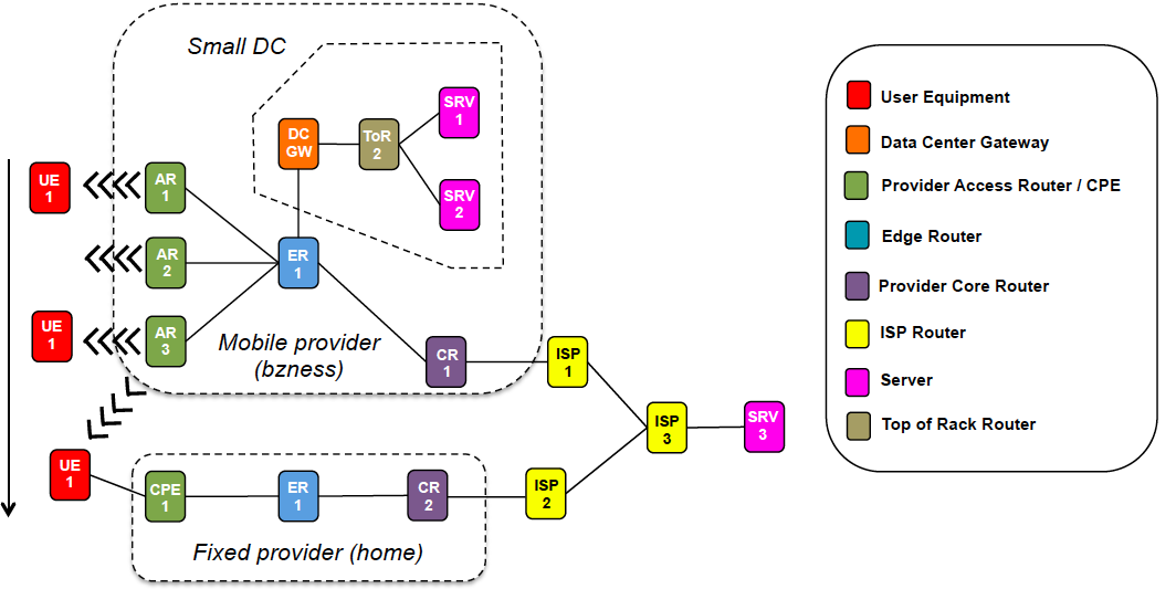
Figure 1 shows a view of the physical systems involved in the experiment. Three Raspberry Pis play the role of WiFi Access Routers (ARs) of the mobile provider network. The three ARs are connected to an Edge Router (ER), which is connected to a Core Router (CR). The CR which connects the service provider network to the Internet via an ISP router. The ER is connected to a Data Centre (DC) gateway, which provides access to a small service-provider owner DC with two servers. The bottom of the Figure shows a fixed provider network, that provides fixed connectivity to the customer CPE router. The fixed provider network is connected to the Internet via ISP2. Both ISP1 and ISP2 are connected to ISP3, which provides access to Server3. All these systems (except for the Raspberry Pis) have been deployed as KVM/QEMU Virtual Machines (VMs).

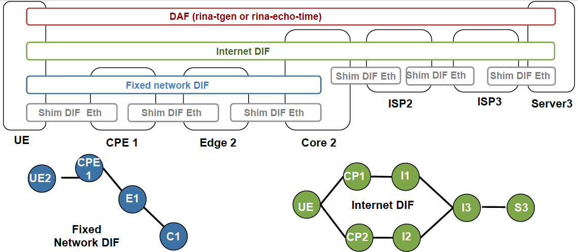
The DIF structure in the mobile network provider is similar to the one shown in Tutorials 9 or 10, the only difference being that there are less access and edge routers. Figure 2 shows the DIF structure at the fixed provider network. The fixed network DIF connects the UE to the core router of the provider, which provides access to the Internet DIF. When doing the handover, the UE is multi-homed to the core routers of the mobile access and the fixed access providers.

A single UE device (a laptop) starts the experiment connected to one of the mobile provider's access routers. The user with the UE device is accessing two applications: one located at the edge datacentre of the mobile provider, running at Server 1 and reachable via the Slice 1 DIF; and the other one running at Server 3 and reachable over the Internet DIF. The user with the UE is travelling home and roams through the mobile provider wireless access routers executing two handovers: AR1 to AR2 and AR2 to AR3. When the user arrives home, it plugs its UE device to the cable that connects it to the fixed provider. The user has a policy configured in its UE device that, whenever the Internet DIF is available through the home provider, this one must be used. Hence, the UE device executes a handover and now it uses the wired interface provider by the home provider to reach the Internet DIF. However, it continues connected to the mobile provider via the WiFi interface, since the home provider does not have access to the Slice 1 DIF.
The first step to get RINA up and running on the Raspberry Pi is to install IRATI as explained in IRATI Raspbian installation. The rest of this section assumes IRATI has been installed within the /usr/local/irati/ folder.
Copy the following IRATI configuration files to the /usr/local/irati/etc folder:
- Main IPCM configuration file: ipcm-exp5mac.conf
- Mobile DIF template: mobile-exp5mac.dif
- Shim DIF over WiFi template: shim-wifi.dif
- Shim DIF over Ethernet template: shim-eth-vlan.dif
Now, assuming the pi user exists on the Raspberry Pi, copy the following files to the /home/pi folder:
Edit /etc/rc.local and add a call to the IRATI init script at the end of the file (so that IRATI will be initialized at boot time).
/home/pi/init-rina.sh
Edit the /etc/default/hostapd file and point it to the /home/pi/hostapd.conf config file (edit the DAEMON_CONF variable):
DAEMON_CONF="/home/pi/hostapd.conf"
If you reboot the Raspberry Pi it should create the VLANs, configure the WiFi interface in AP mode and startup IRATI.
Make sure you create the VLANs indicated in Figure 1, and that you connect the Raspberry Pis and the Machine that will run the Demonstrator with IRATI VMs at the apropriate ports. For example, a possible configuration is:
- AP1 is connected to Eth. switch port 1.
- AP2 is connected to Eth. switch port 2.
- AP3 is connected to Eth. switch port 3.
- UE (when connects to the fixed provider network) is connected to Eth. switch port 4.
- Demonstrator machine is connected to Eth. switch port 8.
Then the following VLANs (which tag the traffic), have to be configured: VLAN 10 on port 1, VLAN 20 on port 2, VLAN 30 on port 3, VLAN 40 on port 4, VLANs 10, 20, 30, 40 on port 8.
Before starting the demonstrator, make sure that:
- You have connected the machine to the VLAN-aware Ethernet switch via the eth0 interface
- You have connected all the Raspberry Pis to the VLAN Aware Ethernet switch and they are up and running
- VLANs have been configured at the switch
The machine where the demonstrator needs to be installed must be a Linux machine and have the bridgeutils and qemu-kvm packages installed. Then copy the pre-configured demonstrator tar.gz file to any folder of your choice, and extract it.
# tar xzvf demonstrator-mac.tar.gz demonstrator
Enter the demonstrator/demonstrator-mac folder and execute the up.sh script:
# cd demonstrator/demonstrator-mac
# ./up.sh
The demonstrator will create the required Ethernet bridges, instantiate VMs, boot them, instantiate IRATI, configure DIFs, trigger enrollments and instantiate rina-echo-time application processes at each one of the "Server" VMs (Figure 1).
TODO
- Home
- Software Architecture Overview
- IRATI in depth
-
Tutorials
- 1. DIF-over-a-VLAN-(point-to-point-DIF)
- 2. DIF over two VLANs
- 3. Security experiments on small provider net
- 4. Multi-tenant Data Centre Network configured via the NMS-DAF
- 5. Congestion control in multi-tenant DC
- 6. Multi-tenant Data Centre network with Demonstrator
- 7. ISP Security with Demonstrator
- 8. Renumbering in a single DIF
- 9. Application discovery and Distributed Mobility Management over WiFi
- 10. Distributed Mobility Management over multiple providers
- 11. Multi-access: multiple providers, multiple technologies