Configuring FF OSD
FF OSD will work well straight out of the box on many systems. However, a configuration menu is available for tweaking OSD position and adapting to different video circuitries:
- Pick a Configuration Method
- Adjust the available Configuration Options
There are several ways to access the configuration menu:
The connection method is the same as for firmware programming. If FF OSD is connected to your Gotek's power then you must not connect your serial adapter's 5V wire.
Use a terminal program such as PuTTY or Python's miniterm utility to connect at 115200 baud, 8 data bits, no parity, and 1 stop bit. Press the FF OSD reset button to view the current configuration and the serial key bindings:
- Space = Select
- O/P = Prev/Next
One advantage of serial configuration is that it can be done immediately after programming, before installing FF OSD into your host machine.
If you have connected FF OSD to your Amiga keyboard you can use the keyboard for OSD configuration.
Press L.Ctrl+L.Alt+Help to enter the OSD menu. The usual key bindings now operate:
- L.Ctrl + L.Alt + Left Arrow = Prev
- L.Ctrl + L.Alt + Right Arrow = Next
- L.Ctrl + L.Alt + Up Arrow = Select
If your OSD is connected to a FlashFloppy Gotek then you can configure OSD via the FlashFloppy main menu using your Gotek's input method.
- Remove any inserted USB stick from the Gotek.
- Press both buttons (or the third button, or rotary encoder).
- Select and confirm the option Configure FF OSD
- Your Gotek buttons and/or rotary encoder are now passed through to FF OSD until you power off, or eject your USB drive or SD card.
Note: This option is unavailable if connected to a FlashFloppy Gotek and with A0-A1 jumpered. Instead you can configure via your Gotek.
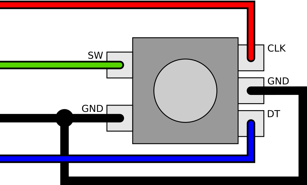
See the encoder pins labelled below, and connect as follows:
- CLK = A0
- DT = A1
- SW = A2
- GND = G
If the encoder operates backwards to what is expected, swap the CLK and DT wires.
Move between the available configuration options by pressing the Select button or key. Use Prev and Next to adjust the currently selected value.
Although configuration values have immediate effect, do not worry if you mess something up: Configuration is not permanently stored until you explicitly Save it in the final configuration step.
If you accidentally Save a bad configuration, you can reset to Factory Defaults by placing a jumper across A1-A2 and reset or power cycle FF OSD.
The available configuration options follow.
Displays the FF OSD firmware version. Press Select to skip to the first configuration option.
Specifies whether CSYNC (or HSYNC/VSYNC) are considered Active when:
- High: commonly used for PAL/NTSC video
- Low: commonly used for VGA
- Auto: attempt to automatically detect the sync polarity
Adjusts the horizontal size of the picture to suit PAL/NTSC or VGA:
- 15kHz (PAL/NTSC): 9MHz pixel clock (SPI1 and SPI2)
- VGA: 36MHz pixel clock (SPI1); 18MHz pixel clock (SPI2)
- Auto: determine pixel timing based on sync signal.
Select the vertial size of the OSD:
- Double: Doubles each row to stretch the OSD vertically
- Normal: Normal display height
FF OSD can output video data on one of two output pins.
- PB15/SPI2: the default video output pin
- PA7/SPI1: supports higher resolution VGA mode NOTE: a change of this option requires a SAVE+RESET to take effect
FF OSD can drive the RGB colour pin with a simple resistor from the SPI output pin. If you want to use an external video buffer or switcher, PA15 is used to drive the buffer's enable pin. This is especially useful if you need a stronger video drive than the STM32 is capable of or if you want to drive the Red and Blue components for a darker background.
- None: default direct connection to the SPI pin
- PA15 Act.LOW: for driving a 74HC540 or 74HC125
- PA15 Act.HIGH: for driving a 74HC126 NOTE: a change of this option requires a SAVE+RESET to take effect
Adjusts horizontal position of the OSD. This can also be altered in real time with an Amiga keyboard (L.Ctrl+L.Alt+A or D).
Adjusts vertical position of the OSD. This can also be altered in real time with an Amiga keyboard (L.Ctrl+L.Alt+W or S).
Note: These options are skipped when using the custom FF protocol.
Select number of rows, and min/max number of columns. The default number of display columns is the configured minimum until the host sends data for a higher column, at which point the display is incrementally extended, up to the configured maximum.
You can select whether to:
- Save the new configuration to Flash
- Save+Reset save to Flash and reset FF_OSD
- Use the new configuration only until power is turned off
- Discard the new configuration and return to previous
- Factory Reset to factory defaults (this is saved to Flash)