Structure of Robot Models
To understand how Phobos represents robots in Blender, it's informative to take a look at URDF (and also SDF) first, the format to which the kinematic data of our Phobos models will ultimately be exported. URDF is a very well-documented format and wherever the information provided here may be missing something or not make intuitive sense, you can have a look at URDF's documentation to get a better idea of how it works. The documentation of SDF you'll find here.
Long story short: A robot kinemtic consists out of links that are connected via joints. Links are then equipped with inertial information as well as entries to represent their visual appearance and (a well computable) representation of their colision shape. Then there may be further information on optical materials, sensors, motors and so on. But if and if yes in which form they exist highly depends on the format (SDF/URDF/SMURF etc.).
To differentiate between those different objects, Phobos adds a new property to Blender objects named phobostype ('link', 'visual', 'collision' ...) When working with Phobos, it's important that each object always has a correctly defined phobostype.
Blender as a 3D modeling software provides elements allowing to store all the data required to represent a robot model. This includes for instance bone objects to define a kinematic skeleton as well as objects containing mesh data for visual representation. While bones allow to directly store relevant information such as joint constraints, not all information required for robots is directly representable with pre-existing elements of Blender. Luckily, Blender allows to assign custom properties to every object in a scene, enabling to store any piece of information in an object. Phobos makes use of this by adding custom properties to existing objects as well as by creating helper objects to explicitly store additional data.
A complete robot model is thus composed of several collections of information, containing numerous kinds of objects, like so:
TODO Check image
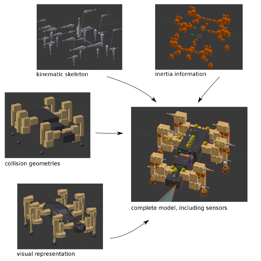
Decomposition of the different elements from which Phobos models are composed in Blender. These elements can be arranged in Blender in different collections, thus avoiding confusion or obstruction of view when editing very complex models.
These information layers are realized as actual collections in Blender, similar to layers in graphical software. Phobos has a default setting to arrange objects of different types to different collections. These are:
- links (joints)
- inertials
- visuals
- collisions
- sensors
- motors
- annotations
The type will determine in which collection objects are placed, imported to or created by various operators. While you can arrange your model to collections as you wish, this might interfere with the function of some operators in a way hardly predictable. Nevertheless, if your model is nicely sorted by types, it's possible to isolate certain types of objects by clicking on the layers below the viewing window (hold down SHIFT to select multiple layers). To move selected objects to a different layer, hit M.
Robot models consist of links defining coordinate frames relative to which objects for visualization and collision detection can be arranged. These links themselves are placed relative to one another as defined by joints, each joint connecting two links.
Links are represented in Blender as armatures containing one single bone. Blender's armatures are designed for building a skeleton of an animated character, consisting of multiple bones which can be linked to one another and constrained in their movement. Phobos in contrast uses one armature object per link, with each armature containing one single bone, which simplifies copying and pasting of entire limbs with their attached visual and collision objects. More info in armatures and bones can be found in the Blender manual.
As joints only define the transformations between links and their constraints of movement, they don't need to be represented as separate objects in Blender, as objects already contain a transformation (to their parent objects). Thus, links in Phobos contain their parent joint's information. Each such armature contains a single bone which in turn stores the constraints defined for the parent joint. In a way it could be said that the armature represents the link whereas the bone represents the joint. This is because armature and bone have their own coordinate systems, which coincide when an armature is newly created, but can be changed later. This is important as URDF/SDF allows to specify the axis of a joint independent of the transform the joint defines to get from its parent to its child link. By changing the orientation of the bone in relation to the armature, the axis orientation in relation to the joint space can be accompanied. This is especially so as the joint axis in Phobos equals the long axis of a bone, making it possible to visualize the axes in a model.
Phobos links (i.e. Blender armatures) can be connected - with joints - by setting up parent-child relationships between them, thus building a tree forming a hierarchical, branching kinematic chain (thus the name link). This way, the model in Blender allows a WYSIWYG (What-you-see-is-what-you-get) approach when emulating robot models.
Blender knows a number of different parenting types depending on the objects to be related. For Phobos, it is essential that you always use the Bone Relative parenting type. we highly recommend that you simply use the Parent Selection button of Phobos.
Further Reading: The reason for this
As stated before, the axis of rotation of a joint is determined by the orientation of a bone. However Blender treats bones as essentially two objects in one: a *pose bone* and an *edit bone*. You might be thinking "Come on, not ANOTHER object!", but this is actually a pretty cool feature. It allows to define a *rest position* of an armature that equals the transform of the edit bones, and a *pose position* that defines an actual pose. Consequently, if you're turning the pose bone, all objects attached to it will turn with it. Not so with the edit bone: If this is changed, you simply change the bone itself and the relations to all attached objects are altered by Blender so they can remain where they are. This, however, only works in the *Bone Relative* parenting mode. Consequently, if you wish to change the rotation axis of a joint after your model has been completed, you simply change the edit bone and that's that - the bone's children will NOT get moved and the rest of your model stays intact. This is pretty handy when constantly having to adapt your robot model to ongoing mechanical design. When an armature is selected in blender, you can switch from "Object Mode" to "Edit Mode" or "Pose Mode" in the toolbar below the 3D view, allowing you to change the edit bone and pose bone.Further Reading: Manual Parenting
Hitting **CTRL** + **P** will show a context menu for parenting which presents the available parenting types, with the one we want to choose at the very bottom. Note that the two types *Bone* and *Bone Relative* are not discriminated between in the *Relations* section of the properties panel on the right. Thus, the only way of making sure two objects use the correct parenting type is to parent them again to one another with the correct type.In robots, there are a number of different joint types, listed as follows those mostly used (taken from the URDF website on joints):
- revolute - a hinge joint that rotates along the axis and has a limited range specified by the upper and lower limits.
- continuous - a continuous hinge joint that rotates around the axis and has no upper and lower limits
- prismatic - a sliding joint that slides along the axis, and has a limited range specified by the upper and lower limits.
- fixed - This is not really a joint because it cannot move. All degrees of freedom are locked. This type of joint does not require any axis, calibration, dynamics, limits or safety_controller.
- floating - This joint allows motion for all 6 degrees of freedom.
- planar - This joint allows motion in a plane perpendicular to the axis.
These joint types can be represented in Blender using the constraint definitions available for bones. Remember that every link is defined using one armature. Each of these armatures contains exactly one bone, which is oriented along the axis that defines the joint. Along or around this axis (depending on the type of joint), constraints can be set to limit the movement of the joint, so that it is not possible to set a joint position in Blender that the real robot is not capable of.
The Define Joints operator allows to choose the type of joint and type in the desired joint limits. As all constraints are defined in the local coordinate frames of the individual bones, multiple identical joints can be set at the same time.
Further types like spherical/ball are planned to be supported in the future.
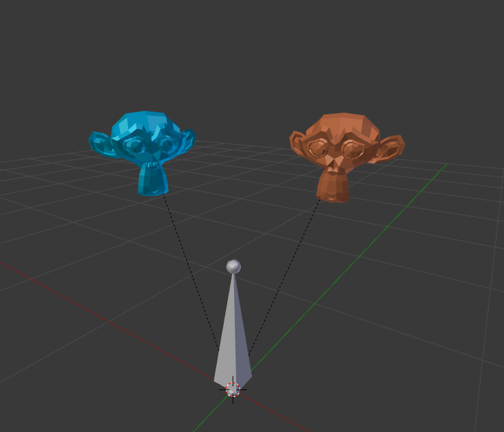
The concept of WYSIWYG using Blender's object hierarchy also extends to visual and collision objects, which define how a model looks like in a visualization and how it behaves colliding with other objects or itself. These objects are defined as children of links in Phobos, they are Blender objects parented to links. Each link can contain multiple visual and/or collision objects, as illustrated in the following figures.
 TODO Check image
An armature with one bone representing a link and two attached visual objects (we used Blender's mascot Suzanne here). The dashed lines indicate parent-child relationships.
 TODO Check image
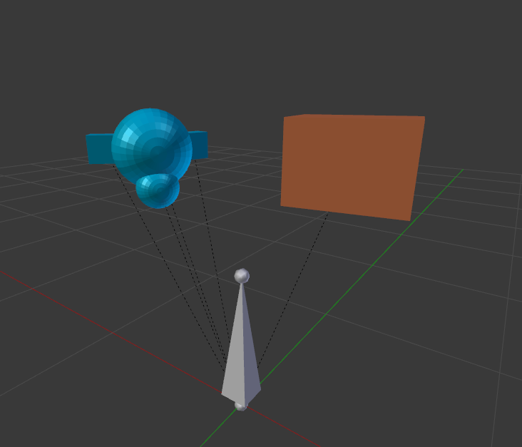
The same link as above, this time with the attached collision objects.
 TODO Check image
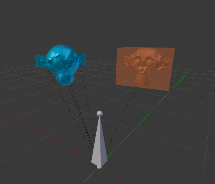
Overlaying both object types illustrates how Blender simplifies approximating the actual robot with a reasonably detailed collision model.
Visual and collision objects are much simpler than links and joints. They are mere 3D-objects containing meshes. Like they were meant to in Blender, you can assign colored and textured materials to visual objects.
There still remain some important details, though. While you can create cubes and spheres etc. in Blender, Blender only keeps track of their geometrical shape upon creation and then forgets about it: all such objects are essentially meshes built from vertices. In order to use the correct geometry type when exporting your robot, we need to assign custom properties to the objects defining their type. This is specified in the custom property geometry/type, which holds strings naming the geometry types in
URDF/SDF ('box', 'sphere'...).
All physical links should be given a mass, center of mass (COM) and inertia tensor (at the COM) of links. To represent this data, Phobos uses inertial helper objects, which contain the data on mass and inertia explicitly and through their transformation store the COM of a link implicitly. Phobos allows to calculate the link inertia information and thus create the inertial objects semi-automatically, as described in the Mass and Inertia section.
Motor specification always relates to an existing joint in Phobos and is stored in a helper object of phobostype 'motor' with the motor's data in it. This object relates to the link/joint which it is parented to.
Sensors are realized in Phobos as objects of phobostype 'sensor'. This is due to them coming in very different forms and thus using (helper) objects is the easiest way to keep sensors consistent as a category while at the same time not limit the flexibility of how they can be realized. For instance, a camera sensor is an actual virtual camera in Blender and a laser scanner is represented as a translucent beam/disc. All data necessary to specify a sensor are stored in its custom properties, with the exception of such data for which Blender has a representation, such as the opening angles for cameras.
To give you the opportunity to store any information you like you can add custom properties. There are two way of doing so depending on where you want to store them.
- You can define custom properties of any object. E.g. if you want to give your motor further annotations like a device id or what ever, you can simply add a custom property to that motor object and it will be exported with the given key and value to the motors SMURF representation. When adding custom properties to links/joints you need to give either the 'link/' or 'joint/' prefix to your property to make sure it will be exported to the correct entity.
- You can add completely custom categories. SMURF is structured in several categories of information e.g. links, joints, motors etc., but you are free to create your own category. Simply use the Add annotation operator to add an annotation object with a category and a name. Again you can add all your custom information to this object and it will be exported accordingly. You can also use information on the parent object and it's location and orientation if you want by checking the corresponding check-boxes and defining properties with a value like $parent or $transform. you can also access the properties of the internal Phobos representation of the parent object or the transform's Pose object. See the details of the representation objects in the API Documentation for their properties.
![]() Back to top.
Back to top.