-
Notifications
You must be signed in to change notification settings - Fork 57
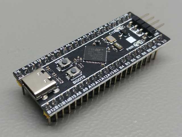
STM32F4 Black Pill
paradajz edited this page Oct 31, 2022
·
2 revisions

- Power: USB C
- MCU: STM32F401CE, STM32F401CC or STM32F411CE
- DIN MIDI: Yes [1]
- LED indicators: No
- Digital inputs: 8
- Digital outputs: 9
- Analog inputs: 9
- Schematic: Link
This board doesn't have DIN MIDI connectors and required additional components so those have to be added to board in order to be used. The following schematic should be used:

Pinout is listed in DIN MIDI section.
| Button # | Pin 1 | Pin 2 |
|---|---|---|
| 0 | A0 | GND |
| 1 | B0 | GND |
| 2 | B10 | GND |
| 3 | A8 | GND |
| 4 | B15 | GND |
| 5 | B14 | GND |
| 6 | B13 | GND |
| 7 | B12 | GND |
| Button # | Pin 1 | Pin 1 | Pin 2 |
|---|---|---|---|
| 8 | A1 | GND with 10k resistor | 3V |
| 9 | A2 | GND with 10k resistor | 3V |
| 10 | A3 | GND with 10k resistor | 3V |
| 11 | A4 | GND with 10k resistor | 3V |
| 12 | A5 | GND with 10k resistor | 3V |
| 13 | A6 | GND with 10k resistor | 3V |
| 14 | A7 | GND with 10k resistor | 3V |
| 15 | B1 | GND with 10k resistor | 3V |
| Encoder # | Pin 1 | Pin 2 | Pin 3 |
|---|---|---|---|
| 0 | A0 | GND | B0 |
| 1 | B10 | GND | A8 |
| 2 | B15 | GND | B14 |
| 3 | B13 | GND | B12 |
| Potentiometer # | Pin 1 | Pin 2 | Pin 3 |
|---|---|---|---|
| 0 | 3V | A1 | GND |
| 1 | 3V | A2 | GND |
| 2 | 3V | A3 | GND |
| 3 | 3V | A4 | GND |
| 4 | 3V | A5 | GND |
| 5 | 3V | A6 | GND |
| 6 | 3V | A7 | GND |
| 7 | 3V | B1 | GND |
| FSR # | Pin 1 | Pin 2 | Pin 2 |
|---|---|---|---|
| 0 | 3V | A1 | GND with 1k resistor |
| 1 | 3V | A2 | GND with 1k resistor |
| 2 | 3V | A3 | GND with 1k resistor |
| 3 | 3V | A4 | GND with 1k resistor |
| 4 | 3V | A5 | GND with 1k resistor |
| 5 | 3V | A6 | GND with 1k resistor |
| 6 | 3V | A7 | GND with 1k resistor |
| 7 | 3V | B0 | GND with 1k resistor |
| 8 | 3V | B1 | GND with 1k resistor |
Note: current-limiting resistors are required in order to avoid damage to the board.
| LED # | Anode | Cathode |
|---|---|---|
| 0 | A15 | GND |
| 1 | B3 | GND |
| 2 | B4 | GND |
| 3 | B5 | GND |
| 4 | B8 | GND |
| 5 | B9 | GND |
| 6 | C13 | GND |
| 7 | C14 | GND |
| 8 | C15 | GND |
| RGB LED # | Anode (Red) | Anode (Green) | Anode (Blue) | Cathode |
|---|---|---|---|---|
| 0 | A15 | B3 | B4 | GND |
| 1 | B5 | B8 | B9 | GND |
| 2 | C13 | C14 | C15 | GND |
| Signal | Display | Pin |
|---|---|---|
| Vcc | Vcc | +3V |
| GND | GND | GND |
| SDA | SDA | B7 |
| SCL | SCL | B6 |
This board doesn't have DIN MIDI connectors so they have to be added to the board with corresponding circuitry. Schematic is available here.
| MIDI In | MIDI out |
|---|---|
| A10 | A9 |
| Screen | Pin |
|---|---|
| Vcc | +5V* |
| GND | GND |
| Rx | A9 |
| Tx | A10 |
Hardware
- Supported microcontrollers
- Supported components
- Pinouts for supported boards
- Recommended components and where to get them
- LED indicators
Configuration and usage
Advanced