-
Notifications
You must be signed in to change notification settings - Fork 57
Supported components
This page lists all possible components which are currently supported by the OpenDeck firmware. Depending on the board variant, some of the listed components may or may not be supported.
- Buttons
- Rotary encoders
- Potentiometers
- FSRs
- Single-color LEDs
- RGB LEDs
- Displays
- DIN MIDI
- Touchscreen
Button is a very simple device which has only two states: on or off. Two of the most common types of switches are momentary and sliding. Momentary is in "on" state while button is pressed. Upon release, state becomes "off". Sliding or "latching" will stay in same state until it's pressed or moved again. Note that momentary buttons can be configured to act as latching ones using Web interface (or raw SysEx).

Momentary switches usually have two or four pins. In four-pin configuration, two pins close to each other are actually duplicates, so there are really only two pins. When connecting, use any two pins from opposite sides. Note that button pins are interchangeable and can be connected in any order.
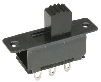
Slide switches usually have 3 pins. Only two pins should be connected: middle and any pin from edge. Depending on which border pin is connected, button will have different state when in left or right position.
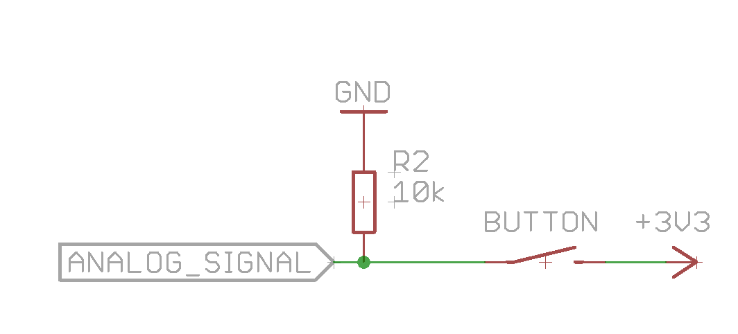
Additional buttons on all boards with OpenDeck firmware can be connected to analog inputs. Note that analog input has to be configured as digital input in Web interface (or via raw SysEx) in order to connect button to it. Button pin connected to signal pin should be also connected to GND via 10k resistor to avoid jumping of values. See the schematic below (note: depending on the board, one of the pins will be connected either to +3V or +5V).
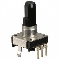
Rotary encoder is a device which converts motion into a certain code (usually Gray code). Rotary encoder outputs two signals, called A and B. Those signals are 90 degree out of phase. This is called quadrature signal. Basically, encoder acts like two buttons with rapid state-switching, so in order to connect encoders on OpenDeck boards, digital inputs are used. Note that encoders, unlike buttons, cannot be connected to analog inputs. Encoder also must be enabled using Web interface (or via raw SysEx). Two inputs are needed to connect single encoder. Rotary encoder has three pins: A and B (left and right or 1 and 3) and ground connection in the middle (pin 2). Note that pins 1 and 3 can be reversed - the only thing that changes in that case is the direction of the encoder.
Potentiometer is a variable resistor. Depending on its position, resistance across potentiometer terminals changes which forms voltage divider. Two of the most common potentiometer types are rotary and sliding potentiometer.
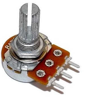
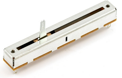
Potentiometer has three pins. On rotary potentiometers, left and right pin need to be connected to positive voltage source and ground. Those connections can be reversed, but potentiometer will change direction in that case. Middle pin is the signal. On sliding and other kinds of potentiometers, refer to datasheet to find the pinout. Recommended resistance for potentiometers on OpenDeck boards is 10k. Note that any analog input must first be enabled via Web interface (or via raw SysEx) because they are all disabled by default. Make sure that all analog inputs which don't have anything connected to them are disabled in order to avoid the board sending lots of junk values due to the floating state of unconnected input.
FSR stands for Force Sensitive Resistor. It is a special kind of resistor which changes resistance when force or pressure is applied to it.
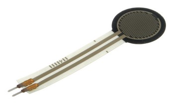
While FSR can be used as standard potentiometer, it is recommended to set analog input on which FSR is connected to FSR type in Web interface (or via raw SysEx). In that case, FSR will act as a button, with velocity being initial pressure on FSR. FSR requires 1k resistor connected between ground and signal pin, the same way as button connected to analog input. While not necessary, it is also recommended to connect external 10nF capacitor between FSR signal and ground for increased stability.
Single-color LED is a simple component which emits light when voltage is applied through anode and cathode.

Anode is usually longer of the two LED pins and cathode is shorter leg. All LED colors are supported.
RGB LED is a combination of three LEDs. Different combinations of three colors are used to produce a new color. In order to use RGB LED, it must first be enabled using software. Note that RGB LEDs come in two configurations: one is common cathode and other is common anode. OpenDeck board supports only common cathode LEDs. In common cathode configuration, the longest LED pin connects to ground, while other three connect to positive voltage source.
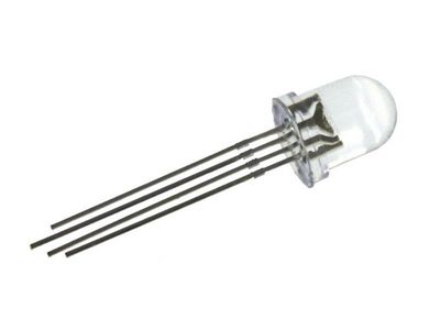
RGB LEDs have four pins.
OpenDeck firmware currently supports the following OLED displays via I2C interface (SPI isn't supported):
- SSD1306, 128x64px
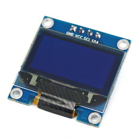
- SSD1306, 128x32px

Note that only one display can be connected at the time.
DIN MIDI uses a classic 5-pin round DIN connector. Many musical instruments feature the connector.

OpenDeck supports all Nextion touchscreen displays.
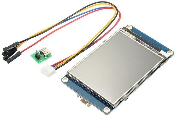
Nextion touchscreen display
Common feature for all supported touchscreens is that they interface with the microcontroller using UART, so only 2 data lines are required: Rx and Tx.
IMPORTANT: For screens larger than 5", regardless of manufacturer, use external power supply. Larger screens draw larger amounts of current which OpenDeck boards cannot provide by themselves. Smaller screens can usually be powered directly from the board if the board provides +5V pin. Always check the screen datasheet for power requirements. Most screens are operated from +5V, however some require larger voltage.
Hardware
- Supported microcontrollers
- Supported components
- Pinouts for supported boards
- Recommended components and where to get them
- LED indicators
Configuration and usage
Advanced